
SUMMARY:
Photon-counting detectors (PCDs) represent a major milestone in the evolution of CT imaging. CT scanners using PCD systems have already been shown to generate images with substantially greater spatial resolution, superior iodine contrast-to-noise ratio, and reduced artifact compared with conventional energy-integrating detector–based systems. These benefits can be achieved with considerably decreased radiation dose. Recent studies have focused on the advantages of PCD-CT scanners in numerous anatomic regions, particularly the coronary and cerebral vasculature, pulmonary structures, and musculoskeletal imaging. However, PCD-CT imaging is also anticipated to be a major advantage for head and neck imaging. In this paper, we review current clinical applications of PCD-CT in head and neck imaging, with a focus on the temporal bone, facial bones, and paranasal sinuses; minor arterial vasculature; and the spectral capabilities of PCD systems.
ABBREVIATIONS:
- CI
- cochlear implant
- CNR
- contrast-to-noise ratio
- EID
- energy-integrating detector
- PCD
- photon-counting detector
- SSCD
- superior semicircular canal dehiscence
- VME
- virtual monoenergetic
Photon-counting detectors (PCDs) are an emerging technology with substantial promise in neuroimaging.1 Conventional energy-integrating detectors (EIDs) use a scintillating layer that converts incident x-ray photons into visible light, and then use photodiodes to record the light photons as electric signal.2 This process has many limitations: EID systems have dose inefficiency tied to the use of interpixel septae and lose substantial signal related to low-energy photons.3
PCD systems, conversely, use a semiconductor to directly convert x-ray photons into an electric signal, and do not require the need to first convert x-rays photons into visible light.4,5 In this process, PCDs uniformly weigh x-ray photons of various energies, thereby providing greater signal to photons that make up the critical aspects of an image.6,7 As such, the scanners do not require interpixel septae, which improve filling factor and dose efficiency at small pixel size compared with EID, enabling dose-efficient ultra-high-resolution imaging.5,8⇓-10 PCD systems also allow the detectors to sort the incoming photons into numerous bins based on their energy. Finally, PCDs are capable of spectral imaging, which can be used to assess for the presence of thyroid cartilage invasion in the setting of malignancy (Fig 1).

Utility of iodine map in detecting invasion of tracheal cartilage in metastatic melanoma. PCD-CT scan of the neck with contrast (A, W/L = −350/−40) and VNC image (B) show a metastatic mass (short arrow in A) with no visible cartilage invasion. On corresponding iodine map image (C), there is involvement of the left first tracheal ring (arrow). Subsequent follow-up image on an EID scanner (D) shows tumor progression at the site of the cartilage invasion with a fistula (arrow). VNC indicates virtual non-contrast. Figure courtesy of Dr. Nitesh Shekrajka.
Together, these features allow PCD-CT scanners to offer numerous benefits over EID-CT scanners, including increased SNRs, superior spatial resolution, less noise, and decreased dose.11⇓⇓-14 PCD-CT scanners also provide higher image contrast-to-noise ratio (CNR), especially for examinations with iodinated contrast media.5 In addition, the use of lower kiloelectron volt virtual monoenergetic images can also boost CNR. These effects allow PCD-CT to use lower iodine contrast while maintaining the same CNR. Similarly, this benefit can also be used to reduce radiation dose. There are other properties of PCD-CT that enable dose reduction. The higher sampling frequency with smaller detector cells in the high-resolution mode allows use of stronger filters during the image reconstruction process. This has been shown to reduce radiation dose at matched spatial resolution, especially for high resolution imaging tasks.10 In addition, other dose reduction capabilities, such as spectral shaping with additional beam filter, have also been demonstrated.
Although still considered a relatively new technology, PCD-CT has already demonstrated benefits for both intracranial and cervical CTA imaging, including reduction of metallic artifacts, identification of spinal CSF-venous fistulas, identification of intracranial aneurysms, and evaluation of in-stent restenosis.11,15⇓⇓⇓-19 Here, we highlight the utility of PCD-CT for various types of head and neck imaging, including evaluation of the temporal bones and paranasal sinuses, visualization of minor head and neck arterial vessels, and spectral imaging.
TEMPORAL BONE
The temporal bone benefits greatly from imaging with PCD-CT. The minute anatomic structures that traverse the temporal bone are often best evaluated on oblique reconstructed planes, e.g., parallel to the superior semicircular canal or along the axes of the ossicles. Not surprisingly, much of the early research on PCD-CT imaging has focused on the temporal bone.
Multiple studies of temporal bone imaging by using PCD-CT scanners have shown that images can be obtained with substantially greater spatial resolution.20 To date, most studies have used Likert scales to show a statistical advantage of PCD-CT over EID-CT imaging. Benson et al,21 for example, used this methodology to show that reviewers preferred PCD-CT images to view multiple specific anatomic structures (e.g., the round and oval windows, modiolus, and interossicular joints) (P < .001). Hermans et al22 similarly used a Likert scale to demonstrate superiority of PCD-CT images in the visualization of multiple temporal bone structures. Already, further studies by using this type of side-by-side Likert methodology are likely unnecessary, because the superiority of PCD-CT images is so clearly self-evident on even a cursory review.
Similar to other anatomic structures, temporal bone imaging on PCD-CT scanners can be performed with significantly less dose and noise. Grunz et al,23 for example, achieved nearly 80% dose reduction when images were matched based on noise. The same study showed that both low and intermediate radiation dose images had significantly less noise than their EID-CT scanner counterparts. Zhou et al24 similarly found that PCD-CT obtained temporal bone images with significantly less noise.
Moving forward, it will be interesting to see how the introduction of PCD-CT into clinical practice will impact the utilization of temporal bone imaging. Characterizations of postoperative changes are much better delineated on PCD-CT images. Furthermore, many of the tiny anatomic structures in the region will be better visualized, or even visualized for the first time. The so-called tympanic segment of the chorda tympani, which courses through the middle ear between the malleus and incus, has long been considered impossible or difficult to identify on CT (Fig 2).25 The distal portion of Jacobson’s nerve, as it splays over the promontory, has similarly been invisible on conventional imaging unless associated with a paraganglioma. Both structures are now readily discernible on PCD-CT.

Visualization of the chorda tympani nerve on PCD-CT. Reformatted sagittal images of the left temporal bone show the mastoid segment of the left facial nerve canal (asterisks). From this arises the chorda tympani: first in its posterior canaliculus segment (solid arrow), and then its tympanic segment in the middle ear (dashed arrows), where it transverses between the malleus and incus. W/L = 1000/4000.
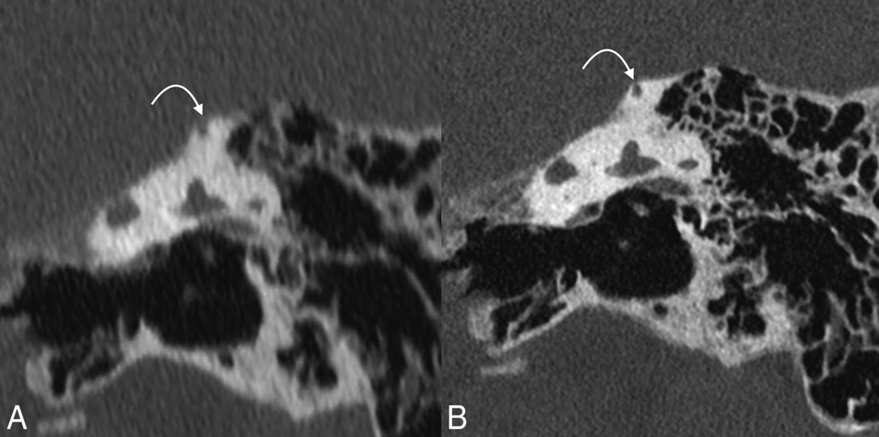
Our ability to diagnose and characterize pathologies will also change. A recently completed study (currently under consideration for publication) found significant differences between images from EID-CT and PCD-CT scanners in the diagnosis of superior semicircular canal dehiscence (SSCD). Specifically, EID-CT scanner images often underestimate the thickness of bone over the superior semicircular canal and overestimate the incidence of SSCD (Fig 3). The anatomic detail captured on PCD-CT imaging will also allow radiologists to precisely assess the involvement of various anatomic structures by different pathologic entities including tumors, cholesteatomas, and labyrinthitis ossificans.

PCD-CT in the evaluation of SSCD. Reformatted coronal EID-CT (A) and PCD-CT (B) images are shown. EID-CT image is highly suggestive of SSCD. PCD-CT image, however, shows a tiny ridge of bone overlying the SSCD (curved arrows on both). W/L = 1000/4000.
PCD-CT imaging is also a promising technology for cochlear implant (CI) imaging. A recent study evaluated the performance of virtual monoenergetic (VME) EID-CT images versus PCD-CT in 2 temporal bone cadaveric specimens with CIs. The images were assessed according to the visibility of interelectrode wire, size of electrode contact, and diameter of halo artifacts. The visibility of interelectrode wire sections was significantly higher when reviewing PCD-CT images. PCD-CT images had larger diameter measurements of the electrode contacts closer to the manufacturer’s specifications for the CI electrode. The size of halo artifacts surrounding the electrode contacts did not differ significantly between the 2 imaging modalities.26
Unpublished data presented at the 2023 Eastern Neuroradiological Society conference comparing T3D (polyenergetic) images and images at different monoenergies (spectral images) in patients with ear implants found that ultra-high-resolution, quantum iterative reconstruction algorithm T3D polyenergetic images were graded the best by reviewers. An inherent disadvantage of the spectral mode is that monoenergetic images are currently limited to a slice thickness of 0.4 mm, which is thicker than the 0.2 mm slice thickness images provided by the T3D images. It is worth noting that this limitation is due to data transfer bottleneck of current implementation rather than the intrinsic limitation of the PCD technology. If the data transfer issue is addressed in the future, 0.2 mm virtual monoenergetic images would be feasible.
Finally, PCD-CT could potentially be used to characterize the spectral properties of cholesteatoma utilizing 3 material decomposition as has been previously done by using dual energy EID-CT.27 Research at our institution on Z effective value of cholesteatoma to help differentiate it from noncholesteatomatous tissue is ongoing.
Facial Bones, Skull Base, Paranasal Sinuses
Compared with the temporal bone, advantages of PCD-CT over EID-CT imaging of the facial bones, skull base, and paranasal sinuses have gone comparatively unheralded in the literature. Nevertheless, the benefits of PCD-CT imaging are the same: the scanners can produce higher resolution images at a lower radiation dose. Use of tin prefiltration on a PCD can even more dramatically decrease the radiation dose. Grunz et al,28 for example, found that ultra-low radiation exposures of 0.08 mGy (calculated for a 16-cm head phantom) were adequate for some inflammation-focused paranasal sinus imaging. Rajendran et al,29 also by using a tin filter, were able to achieve a mean dose reduction of 67% when imaging the paranasal sinuses.
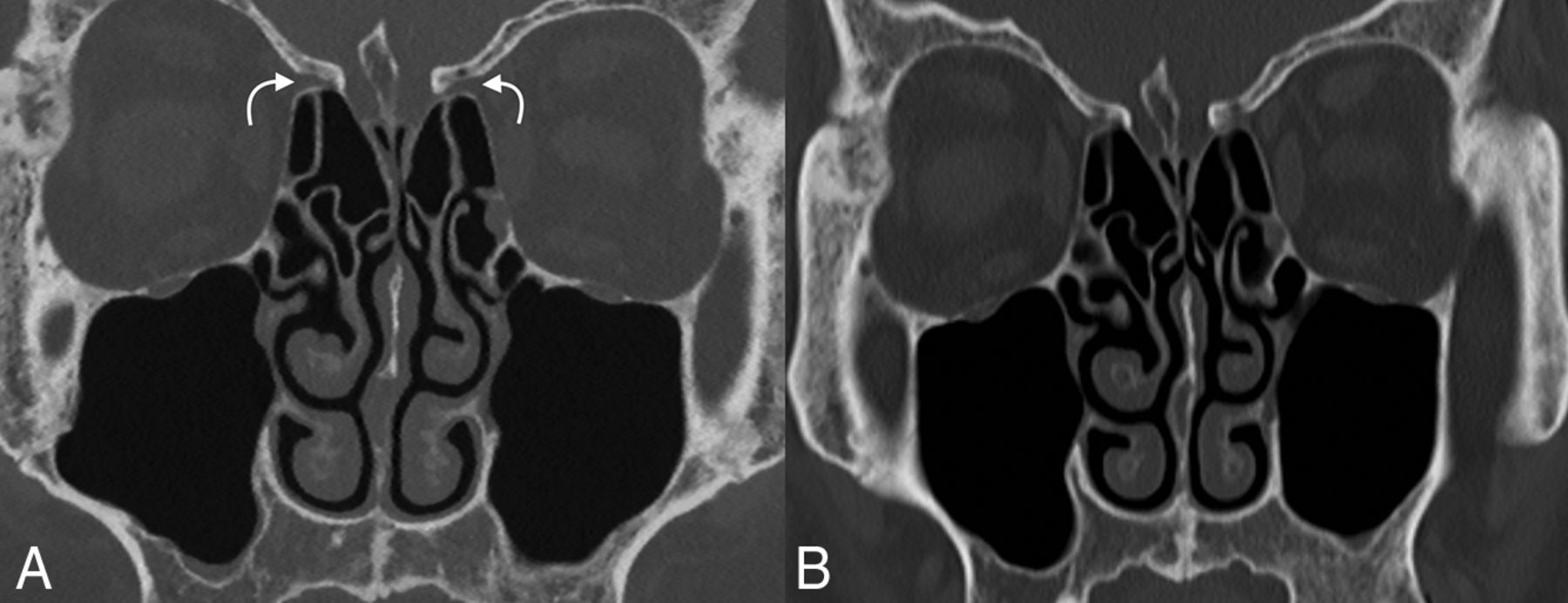
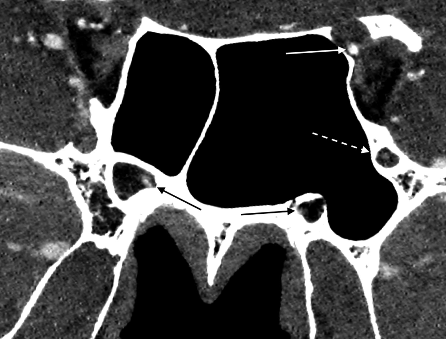
The superiority of spatial resolution achieved by PCD-CT scanners is particularly useful when assessing the smaller structures in the sinus and midface regions, e.g., the osteomeatal units, anterior and posterior drainage pathways, facial foramina, and pterygopalatine fossae (Fig 4). Imaging performed on PCD-CT scanners shows superior visualization of numerous “critical” anatomic structures, including the lesser palatine foramina, anterior ethmoidal artery canal, and nasomaxillary sutures.29 High-resolution 3D reformats of the facial bones are useful when assessing for fractures in the setting of midface trauma. The anatomic detail afforded by PCD-CT imaging allows for more confident evaluation of the structures of the skull base (Fig 5). Indications such as CSF rhinorrhea should benefit from the high-resolution imaging afforded by PCD-CT, including in the evaluation of the integrity of structures such as the cribriform plate and fovea ethmoidalis.

Comparison of PCD-CT to EID-CT in paranasal sinus imaging. Although both are useful for the relatively larger anatomic structures of the paranasal sinuses, PCD-CT image (A) has substantially greater spatial resolution at less radiation doses than EID-CT image (B). For example, the anterior ethmoidal artery notch is seen much clearer on PCD-CT image (curved arrows). W/L = 575/3630.

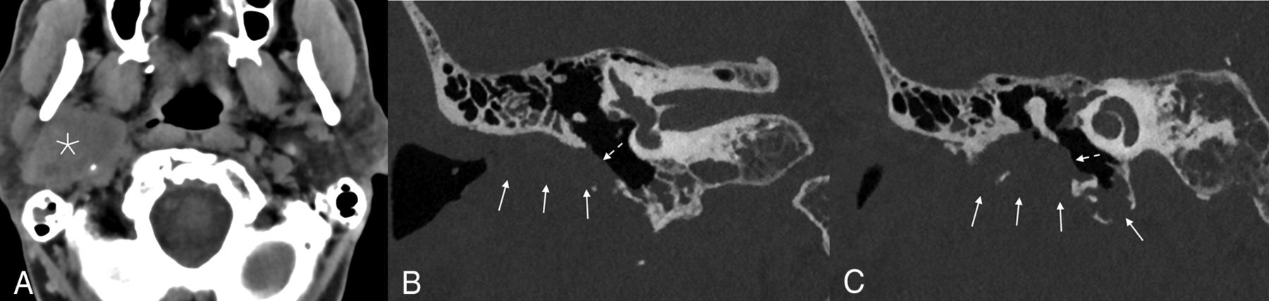
Example of an adenoid cystic carcinoma with invasion of the skull base in a 69-year-old man. A large soft tissue mass was seen centered in the right parotid gland (asterisk). Coronal bone kernel images demonstrated invasion into the right temporal bone with involvement of the external auditory canal (arrows), abutting the tympanic membrane (dashed arrows), and abutting the handle of the malleus. A = soft tissue kernel, W/L = 51/337. B and C = bone kernel, W/L = 1000/4000.
Similar to imaging of the temporal bone, facial bone, skull base, and paranasal sinus imaging could be affected by the proliferation of PCD-CT scanners. For example, the improved anatomic details captured by PCD systems could increase the sensitivity of imaging to evidence of early tumoral spread or invasive fungal sinusitis. Tiny facial bone fractures may also become much more discernible on imaging. For now, however, these prospects remain unproven. In our experience, PCD-CT images seem superior to EID-CT images in facial bone imaging, though the higher spatial resolution in this area may not dramatically change most day-to-day clinical practices. Future studies will be needed to assess how much, if any, benefit if derived by using PCD-CT in imaging of facial bone pathologies.
HEAD AND NECK ARTERIAL VASCULATURE
PCD-CTA improves visualization and characterization of vasculature abnormalities compared with that possible with state-of-the-art EID techniques. Many of the angiographic capabilities of PCD-CT scanners are related to the large- and medium-sized arteries of the cervical and intracranial arterial vasculature and are beyond the scope of this article. In brief, however, authors have already shown that PCD-CT is better able than EID-CT to delineate extra- and intracranial arterial vasculature, with better spatial resolution and decreased partial volume effects on MIP images.30 Studies have also found that PCD systems are able to achieve a higher intravasculature iodine contrast attenuation and decreased beam hardening related to osseous structures of the skull base and cervical spine.8,31
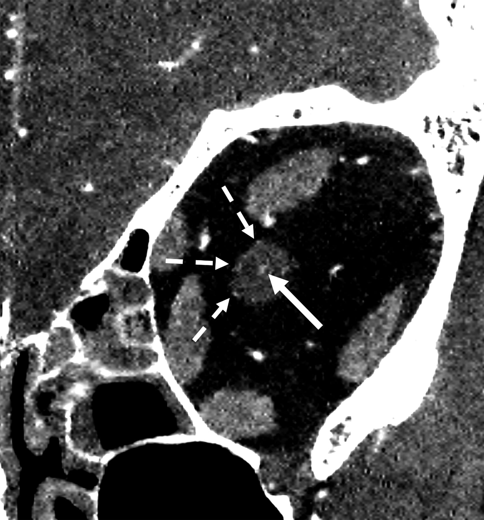
Recently, Farnsworth et al32 reported on the use of PCD-CT images to evaluate orbital arteries, in which the authors showed a considerable level of angiographic anatomic detail. Among its impressive findings, the study demonstrated clear delineation of the central retinal artery, long and short posterior ciliary arteries, anterior ciliary arteries, supraorbital artery, arterial supplies of the extra-ocular muscles, superior and inferior medial palpebral arteries, and the anterior and posterior ethmoidal arteries. Our own efforts to replicate such high-resolution arterial imaging with PCD-CT have been successful (Fig 6). Similarly, we have been able to evaluate numerous tiny arterial vessels in multiple face and skull base foramina (Fig 7). However, the central retinal artery is still inconsistently visualized on PCD due to its diminutive caliber and its nonvisualization does not automatically infer pathology.

Evaluation of a central retinal artery on PCD-CT. Coronal CTA image of the midleft orbit from a PCD-CT scanner demonstrates both the central retinal artery in the distal optic nerve (solid arrow) and branches of the posterior ciliary artery (dashed arrows). W/L = 219/48.

Arteries in multiple skull base foramina on PCD-CT. A reformatted coronal CTA image through the sphenoid sinuses exemplifies the ability of PCD-CT to evaluate the left ophthalmic artery (solid white arrow), foramen rotundum artery (dashed white arrow), and pterygoid canal artery (solid black arrows). W/L = 262/88.
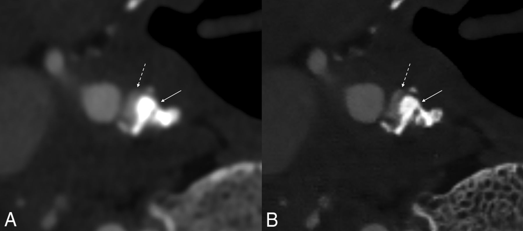
Characterization of tiny head and neck vessels could potentially be clinically useful. As Farnsworth et al32 noted, diagnoses made on high-resolution PCD-CT images might obviate the need for interventional angiography. Improved identification of collateral pathways could modify the treatment of certain vascular conditions. In addition, images obtained on conventional EID-CT scanners tend to overestimate the degree of arterial stenosis caused by calcified atherosclerotic plaques due to blooming artifact (Fig 8).33 Thus, PCD-CT images will be better able to predict the degree of atherosclerotic stenoses in these vessels accurately. Finally, identification of head and neck vasculature could conceivably help radiologists more accurately recognize pathologic processes such as perineural tumoral spread by showing mass effect upon or direct invasion of minor adjacent arteries.

Example of improved vessel lumen conspicuity in the setting of a calcified atherosclerotic plaque. Blooming artifact–related densely calcified plaque at the origin of the right ICA (arrow) somewhat obscures the adjacent lumen (dashed arrow) on EID-CT, scanned with 0.6 slice thickness (A). PCD-CT image (at 0.2 mm slice thickness) provides substantially better evaluation of the lumen (B). W/L = 810/216 on EID-CT, 868/2220 on PCD-CT.
PCD-CT does not come without challenges. There are some nonideal physical aspects of PCD-CT that could impact its performance, such as pulse pileup, charge sharing, and k-escape.5 In addition, the ultra-high resolution could result in high image noise, which has to be appropriately addressed with denoising algorithms to take full benefit of the high-resolution capabilities. From a clinical workflow perspective, the large amount of data and different image types generated by PCD-CT also require appropriate data management and compatibility with downstream image processing software.
CONCLUSIONS
PCD systems have the potential to radically transform head and neck imaging. CT scanners by using PCDs generate images with substantially superior spatial resolution, improved iodine CNR, and reduced artifact, all at a lower radiation dose. As this technology continues to expand into clinical practices, the onus is on clinicians to adapt to this emerging technology. This will require greater knowledge of minute anatomic structures, some of which were previously unidentifiable on conventional EID systems, awareness of the spectral capabilities of PCD-CT scanners, and a commitment to optimize the technology to further reduce radiation doses.
Footnotes
Disclosure forms provided by the authors are available with the full text and PDF of this article at www.ajnr.org.
References
- Received December 15, 2023.
- Accepted after revision February 12, 2024.
- © 2024 by American Journal of Neuroradiology


Jump to section
Related Articles
Cited By...
- No citing articles found.