
Abstract
Summary: We compared eight spinal needle biopsy procedures performed with an investigational disposable real-time stereotactic device and eight spinal needle freehand biopsies in which a standard technique was used, to determine whether the investigational device added value to the procedure. The device uses a simple stereotactic diaphragm pattern to define two vector points. The procedures in which the device was used were completed in 38% less time, using 50% fewer images, with considerably improved spatial accuracy and increased operator confidence, despite the device learning curve.
An inexpensive time-saving approach to stereotaxis could provide the radiologist with an alternative to fixed-frame stereotactic or computer virtual techniques now used for most surgical percutaneous biopsies (1–3). Many stereotactic devices have been designed for assisting CT-directed procedures, but few are widely used since they normally add only cost, rather than adding value in terms of user confidence and accuracy or safety of the procedure (4–10). To be successful in a routine clinical setting, a stereotactic method should be easy to understand, flexible, and fast. The approach to a procedure with the investigational device used herein is considerably different from that used with most stereotactic neuroradiology procedures performed by neurosurgeons. Most neurosurgery procedures use expensive proprietary hardware and software for studies that are actually completed outside the radiology department, usually in an operating room environment. It is difficult to justify the use of this type of procedure based on the reimbursement of a routine spinal biopsy.
Our goal was to overcome prior stereotactic device limitations and to determine whether the investigational device could be used to increase patient safety (by allowing a reduction in number of required scans and radiation dose and by improving spatial accuracy), reduce overall examination time, reduce the number of needle manipulations required to attain a target, and increase the confidence of the radiologist performing the procedures.
Technique
An investigational image-guided stereotactic device that is inexpensive, disposable, simple to use, and nonelectronic was used for eight spinal-needle biopsy procedures, and results were compared with those obtained in eight comparable spinal needle biopsy procedures performed with a routine freehand technique (Table). Routine CT scanning parameters were used for all studies, including a 28-cm field of view, 512 × 512 matrix, 1-second scanning time, and 3–10-mm section thickness. Each patient group consisted of four men and four women, with similar age statistics (freehand group age range 44–83 years, mean 55 years; device-assisted group age range 42–80 years, mean 59 years). The depth of the target was similar in both groups (73.1 mm with the device, 79.8 mm freehand). With use of the initial targeting image as a baseline, number of scans, elapsed time, and accuracy were determined for each group, and results were compared. Device-assisted procedures were performed under an investigational review board study, and all patients provided written informed consent. The usual indication for biopsy was either infection (diskitis, osteomyelitis) or tumor (primary, metastasis).
Comparison of the freehand technique with the stereotactic device technique
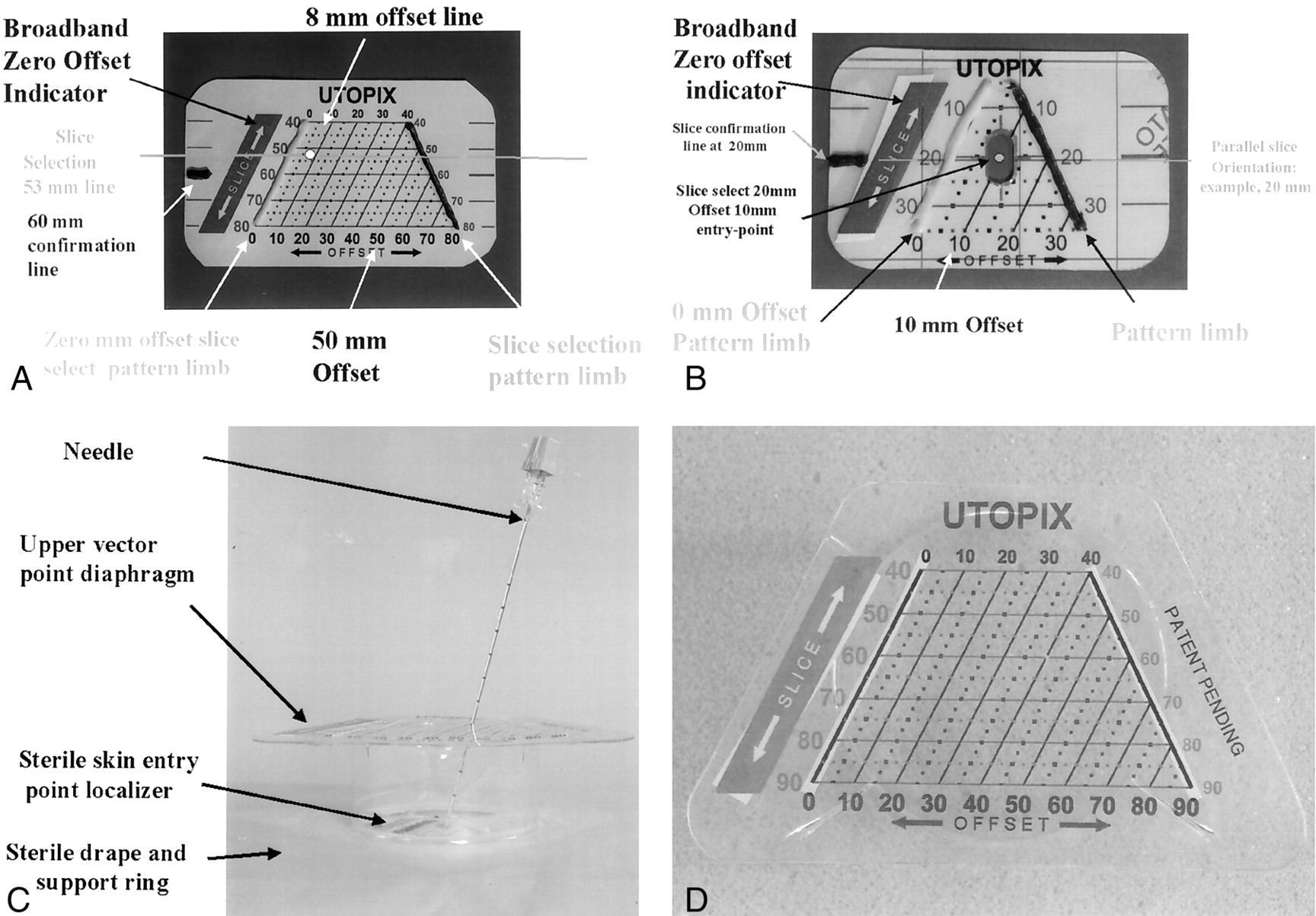
The three-component investigational device (3D Vector Guide; Utopix, Columbus, OH) is a simple localization and aiming device for routine needle placement or drainage procedures (Figs 1 and 2). The device defines two points that determine the targeting vector, one on the skin and a second on a structure above the patient. We used two different but similar device variations. Only one is described, but each uses the same procedural steps. The device is compatible with any needle system. All device components incorporate a patented pattern with an image-conspicuous millimeter-scaled pattern grid. This pattern has a geometric property that provides the user with three-dimensional positional information on the two-dimensional pattern, having an easy-to-interpret, two-coordinate point definition capability, similar to an (x, y) coordinate, that is independent of gantry angulation. The pattern is a truncated isosceles triangle in an inverted V form with an angle of 53°. The sides of the triangle are referred to as the pattern limbs, with one pattern limb (the zero reference limb) wider than the other to provide right-left orientation information. A nonsterile opaque adhesive paper pattern grid (entry-point locater) is placed over the approximate area of entry parallel to the image section plane and imaged with the patient (Fig 1A). On the image chosen for targeting, a measurement of the distance between the image-conspicuous pattern limbs precisely defines the image section plane location (ie, if the image-measured interlimb distance was 44 mm, the image section plane location was along the 44-mm slice line on the pattern grid on the patient). This is the slice coordinate. With use of this same image, the second coordinate of the desired skin entry point along the slice section is determined by measuring the distance from the zero reference pattern limb to the chosen skin entry point (offset coordinate) (Figs 1A and 2A). A marking pen is used to puncture the pattern at that point on the pattern and mark the patient’s skin, and a line is drawn on the patient’s skin.

Device components.
A, Nonsterile skin entry localizer is composed of two image-conspicuous lines (barium impregnated silicon) in a truncated inverted V-shaped triangular configuration. The millimeter distance measured between the two V limbs of the pattern is equal to the actual image section plane location on the printed millimeter scale. The pattern has a thicker image-conspicuous band paralleling the radiologic right V limb that is used as a right-left reference. The radiologic right V limb is the 0-mm reference. A series of offset lines at 10-mm increments are printed on the pattern. The intersection of the chosen vector with the pattern is defined as a specific point on the pattern by the two coordinates (slice select, offset). In this example, the skin entry point located at slice select 53 mm and offset 8 mm is marked with a pen.
B, Sterile skin entry-point localizer. The center of this pattern is centered over the predefined marked skin entry point.
C, View of the upper vector point components parallel to the skin. The device comes with an incorporated sterile adhesive drape and a circular opening with an attached base ring to support the upper level pattern platform.
D, View of the upper vector point localizer seen from above. The upper vector point localizer has a clear diaphragm pattern and printed scale that is used in a manner identical to that of the skin point localizer.

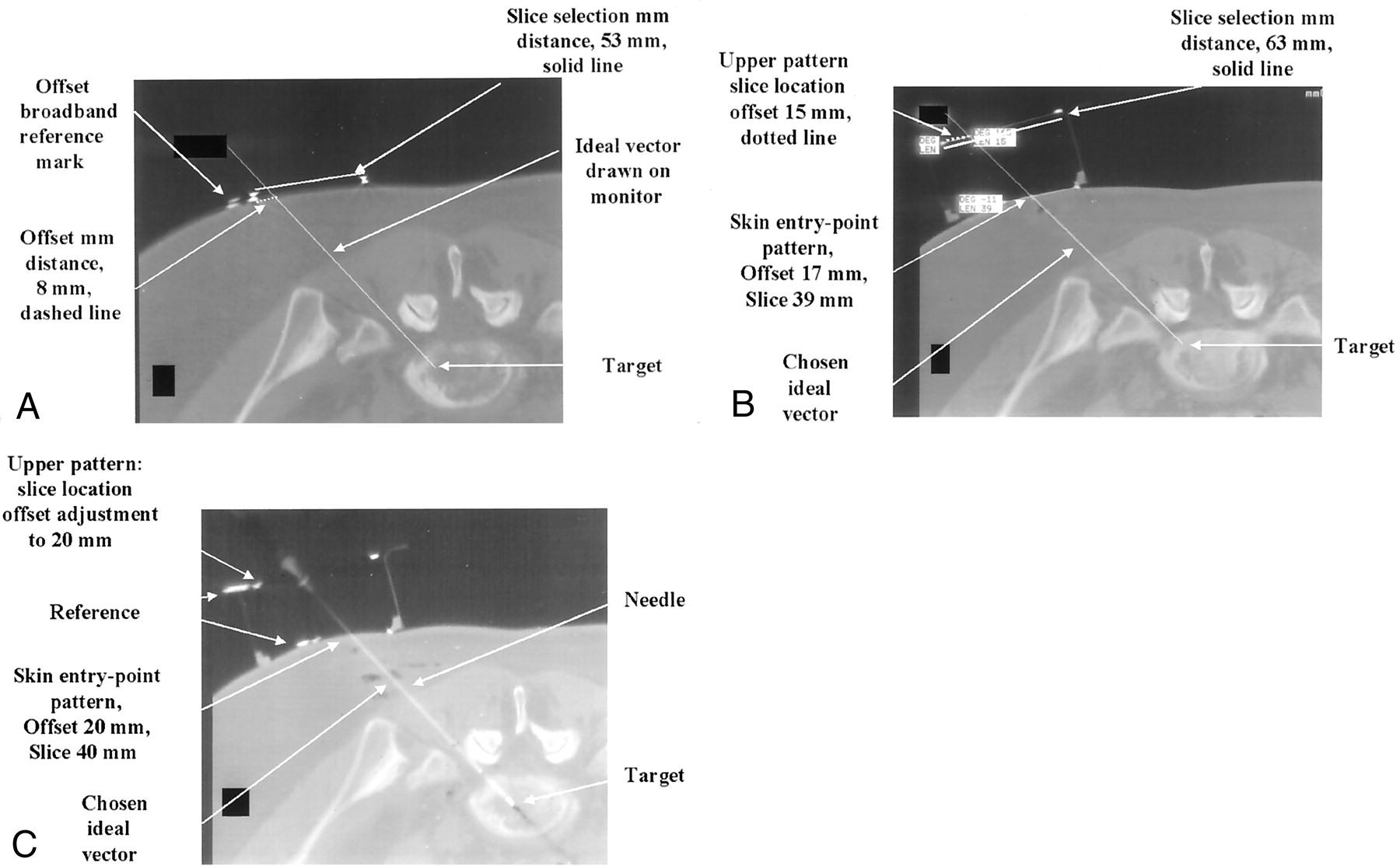
Diaphragm device—assisted procedure.
A, A 3-mm axial CT image with a 19° angle gantry tilt. This is the planning image for the procedure, with the goal to biopsy the L5-S1 level. An ideal vector is drawn from the target to the skin. Nonsterile skin entry-point pattern is seen as two hyperattenuating dots. The distance measured is 53 mm and defines the entry-point slice select coordinate. The second coordinate offset value is 8 mm. The skin entry-point localizer is punctured at this point and lines are drawn parallel to the slice on the patient’s skin.
B, First poststerile CT image with the multilevel device placed over the target. The sterile pattern localizer is seen as two small hyperattenuating dots on the skin. The ideal targeting vector is drawn on the monitor, and its intersection point with the upper level pattern component is measured. The slice location is 63 mm and the offset 15 mm. The diaphragm is punctured at this point, and the needle is placed at the predefined skin entry point. After one adjustment, the needle is advance the measured depth to the target.
C, CT image shows the needle entering the target along the predefined vector. The upper diaphragm was sliced, allowing the probe to pass through the diaphragm to reach the target. Despite the complex double oblique vector, the entire needle is visible, demonstrating the accuracy of the device.
Once the skin has been sterilely prepared, a smaller, similar sterile transparent adhesive pattern is centered on the chosen skin entry point parallel to the section plane. A sterile drape with an upper device support ring is placed over the entry point. The upper vector point pattern diaphragm component is placed over the entry point parallel to the image section plane centered approximately over the desired targeting vector, and the patient is again imaged (Fig 2B). The desired targeting vector is redrawn on the monitor, originating at the target point, passing through the chosen defined skin entry point and extending through the upper device pattern grid. The point of intersection of the targeting vector with the upper pattern grid is again defined on the image on the monitor with the two coordinates (slice, offset). The needle is placed through the upper vector point diaphragm at that location and then advanced through the chosen skin entry point and into the patient approximately 1 cm. An image is obtained to confirm correct vector alignment. If any adjustments are needed, the process is repeated.
The distance from the needle tip to the target is measured on the image, and the needle is advanced the measured depth to the target. It is helpful to rotate bevel-tipped needles or small-caliber needles as they are advanced, to reduce the tendency of the needle to veer off course. Any needle can be held in position by the system.
The procedures in which the device was used were found to be completed with a 38% reduction in time (25 minutes with device vs 37 minutes freehand) with 50% fewer images (seven images with device vs 14 images freehand) and greater spatial accuracy (device skin entry-point accuracy was 0-mm discrepancy from planned vs 4.5-mm freehand entry-point discrepancy, and device target acquisition was 1.6-mm error from planned vs 4.8-mm error in the freehand procedures).
Discussion
Most spinal CT-directed biopsies are performed freehand, without any stereotactic assistance. Most neuroradiologists are experienced in these procedures, and the procedures are performed by using operator experience and a trial-and-error approach to reach the final goal. Spinal biopsies are frequently more challenging than many other biopsies because the targeting vectors are usually double oblique, the targets are small, the accuracy must be high to avert injury to adjacent structures, and they involve the bone. For a stereotactic device to be successful, it must be inexpensive enough to add value to the procedure, without exceeding the financial limits of expected revenue for the procedure. The device and the device-assisted procedure must be flexible to accommodate any adjustment necessary to respond to potential events occurring during the procedure (ie, patient motion or change in plan). It must be easy to understand and use so as to be easily incorporated into a routine clinical practice setting without the need for extensive training. The system should also be scanner independent, with no need for special software or other proprietary scanner hardware.
We developed a simple nonelectronic disposable stereotactic device to assist the radiologist in completing these challenging procedures. The utility of an investigational device is based on its ability to accurately define two points that determine the ideal targeting vector for the procedure (one on the patient’s skin and the other on a pattern supported above the patient’s skin) and to support the needle along the trajectory during the procedure. This characteristic is independent of gantry angle. It is also significant and helpful that this geometric characteristic is independent of the slice thickness, allowing targeting vector definition with a 1-mm accuracy even within a 10-mm slice, avoiding the common problem of being unable to visualize a needle entirely within an image section plane slice.
Although we used two different device prototypic designs and had multiple operators learning to use the device during the procedure, we found that the procedures performed with the device required fewer images and less procedural time and were more accurate in terms of reaching the goal of exact spatial definition of the vector (Table). The main reason for this was that the device generated precise spatial information that could be translated into procedural steps. For example, the first three procedures that were performed with the device were completed with only three images each. The entry point was defined, confirmed, and marked based solely on the initial image. This would be impossible with a freehand technique. Also, in three cases, the first image after sterile preparation was used to completely define the targeting vector (defining both the skin entry point, the upper device level vector point, and the depth to the target). These measurements were then translated into actual needle alignment along the vector and advancement to the target. A third image was used only to confirm the correct final position of the needle in the target along the vector. It is possible to analyze a single image with the device in place on a patient and to precisely define a needle trajectory along a preferred vector path in one step (with four simple coordinate measurements taken from the image of the locations of the two vector points).
Because each image with the device encodes the position of the target and the device, patient movement is not a problem. Any change in patient positioning will be reflected in the next image, and any adjustment necessary to correct a target vector error can be precisely measured. In general, movement was only a few millimeters, but even if there had been more motion, it would have been simple to continue the procedure without interruption because the true location of the vector was encoded on the prior image and the gantry was aligned with the device (instead of the patient having to stay in alignment with the laser light as is necessary in freehand procedures).
Because many spinal procedures use a gantry tilt, defining the plane of the needle and keeping it parallel to the image section plane is difficult with a freehand technique. With this device, the degree of gantry tilt is not important. The needle was frequently completely visible within the image section plane on the final image, implying that the device was accurate in defining both the image section plane and the vector coordinates. In the freehand procedures, once the needle left the section plane, recovery of position and appropriate correction necessary for this recovery were more difficult and a matter of trial and error. A few millimeters of error in trajectory at the skin level can lead to a substantial error in targeting precision after only a few centimeters of needle advancement.
It may be possible to perform and possibly to improve other radiologic procedures by using this device, in terms of increased accuracy and reduced time, and to direct more complicated procedures such as brain biopsies, drug delivery, or ablative therapy. The diaphragm device design also has the potential to allow the operator to sequentially place several needles or probes to a single target, to immediately perform a second biopsy at the same site, or to biopsy several small targets simultaneously (potentially useful in sampling tumor margins). All of these more invasive interventional procedures require substantially more spatial accuracy than that possible with routine freehand biopsy.
- Copyright © American Society of Neuroradiology
In this issue


Jump to section
Related Articles
Cited By...
- No citing articles found.