
Article Figures & Data
Figures
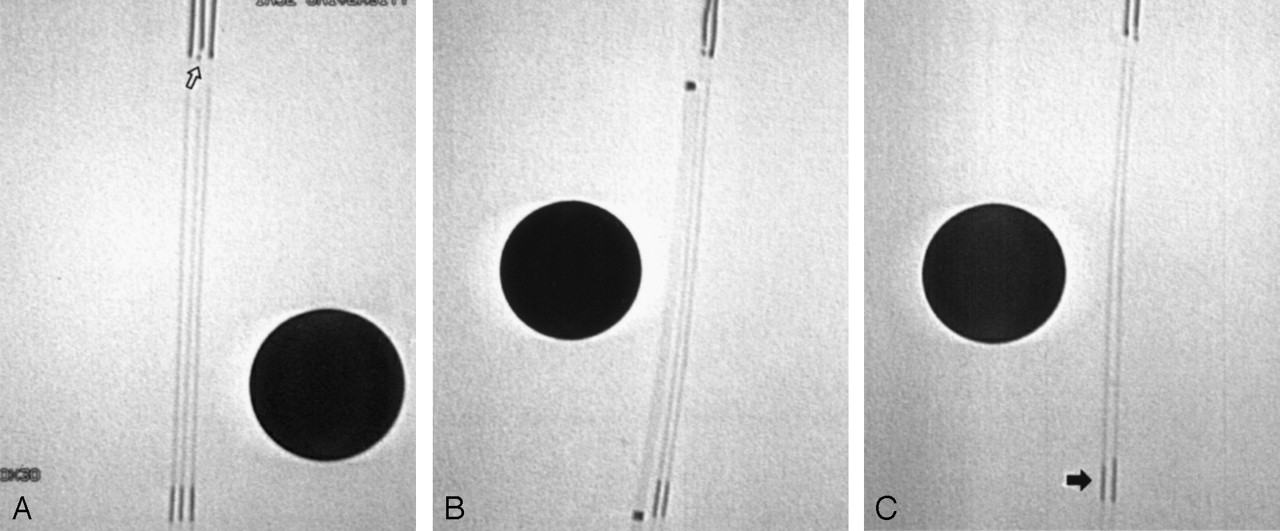
- Fig 1.
Fluoroscopic images show distance from proximal end of coil maker to detachment zone of GDC. The diameter of the black circle is 1 cm.
A, Distance from proximal end of coil maker to detachment zone of SynerG GDC is approximately 0.2 to 0.3 mm shorter than that of non-SyngerG GDCs. Note the small transparent zone near the real detachment zone (arrow) of the SynerG GDC.
B, Fluoroscopic image shows same distance from proximal end of coil maker to detachment zone in both SynerG and non-SynerG GDCs. The microcatheter is an Excelsior. Note the marker alignment and the position of the coil detachment zone from the catheter tip.
C, GDC has shorter marker (arrow). Despite the shorter length, the distance from the proximal end of the coil maker to the detachment zone is similar to that of another GDC.
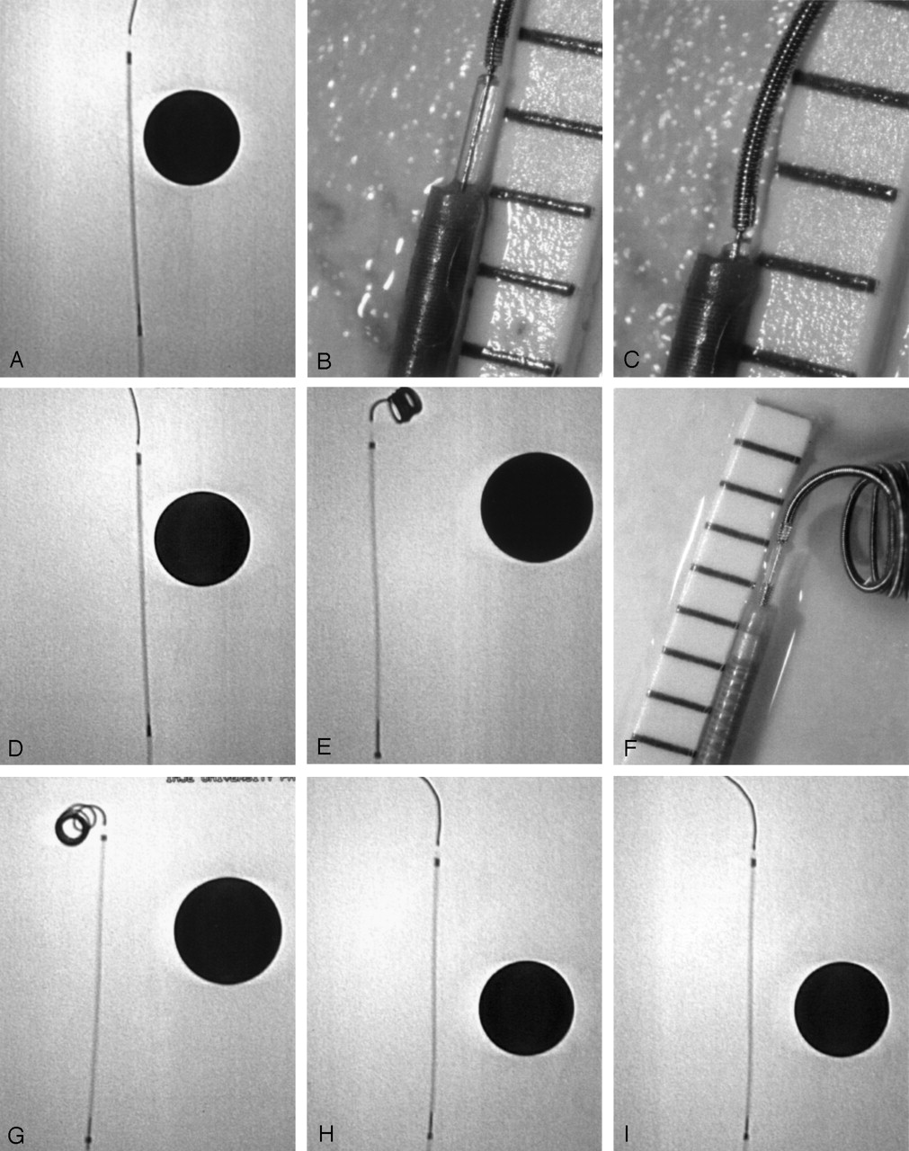
- Fig 2.
Photographs and fluoroscopic images show proximal and distal catheter markers, catheter part extended from distal catheter marker (real end of microcatheter), and distance between catheter markers. The diameter of the black circle in the fluoroscopic image is 1 cm. A division of the ruler shown in the photographs (A and C) is 1 mm.
A, Photograph shows proximal catheter markers. From left: Excel-14, Rebar-14, Excelsior, Prowler-14, and FasTracker-10.
B, Photograph shows that one Excel catheter (left) has longer catheter part beyond distal catheter marker than that of Excelsior (right). It measured 1.68 mm.
C, Photograph shows proximal catheter markers. The distal ends of the microcatheters are arranged in the same position as shown in A. Arrow indicates the distal parts of the catheters.
D, Fluoroscopic image shows relative locations of proximal catheter markers when distal ends of microcatheters are arranged in similar positions. From left: Excel-14, Rebar-14, Excelsior, Prowler-14, and FasTracker-10.
E, Fluoroscopic image shows that one Excelsior has shorter marker distance than another Excelsior. From left: Excelsior, Excelsior, and Excel-14.
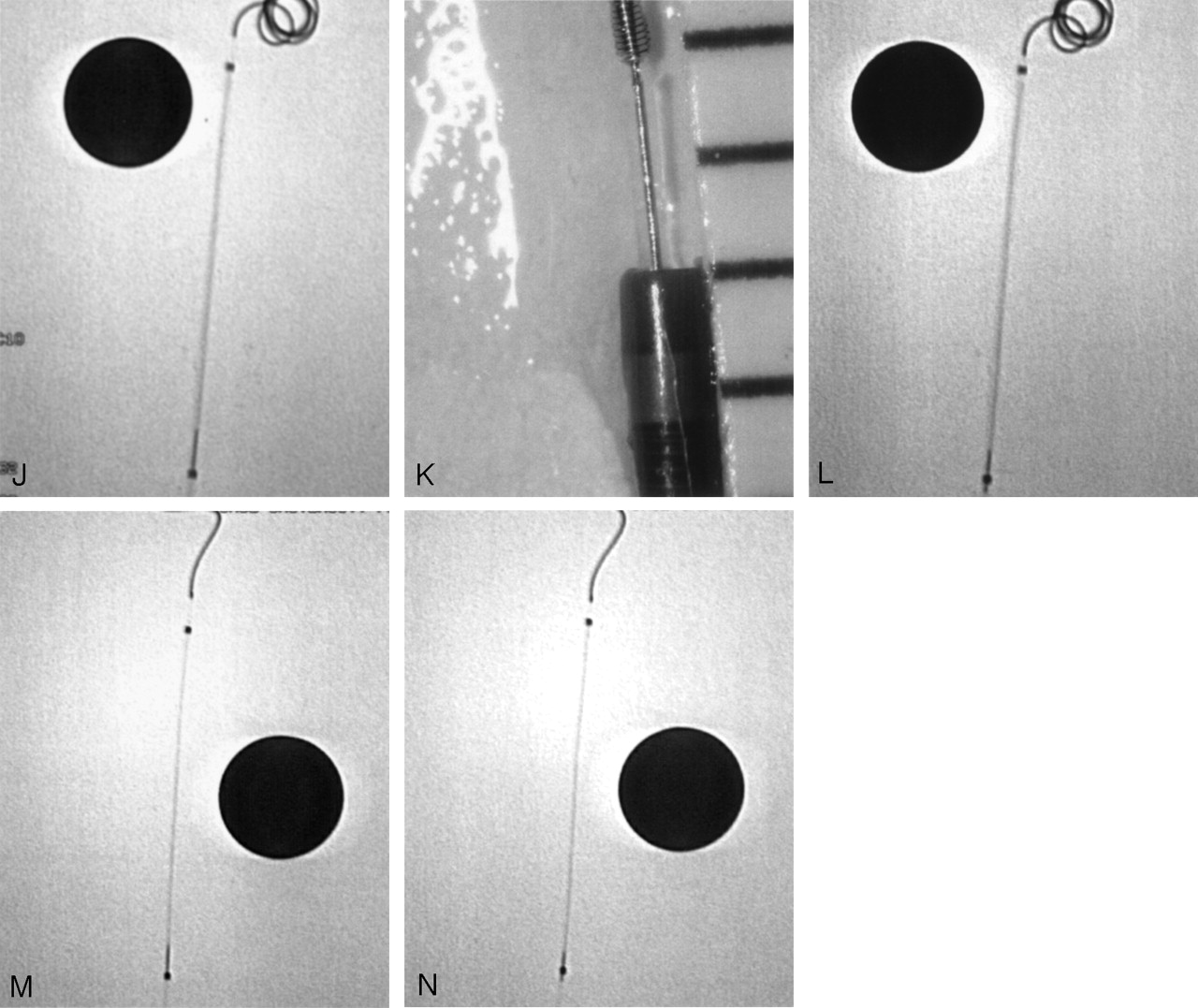
- Fig 3.
Photographs and fluoroscopic images show position of coil detachment zone with usual marker alignment and marker alignment at ideal alignment. The diameter of the black circle in the fluoroscopic images is 1 cm. A division of the ruler shown in the photographs (B, C, and F) is 1 mm.
A, Fluoroscopic image shows usual alignment in Prowler-14.
B, Photograph shows position of coil detachment zone in this alignment.
C, GDC is retrieved to ideal alignment.
D, Proximal end of coil marker is aligned with proximal end of proximal catheter marker.
E, Marker alignment and position of coil detachment zone in Excel-14 (fluoroscopic image).
F, Marker alignment and position of coil detachment zone in Excel-14 (photograph).
G, Ideal alignment in Excel-14.
H, Marker alignment and position of coil detachment zone in Rebar-14.
I, Ideal alignment in Rebar-14.
J, Marker alignment and position of coil detachment zone in Excelsior.
K, Marker alignment and position of coil detachment zone in Excelsior. An Excelsior that has a 0.5-mm-shorter marker distance than the other Excelsior catheters (see Fig 2E) is used.
L, Ideal alignment in Excelsior.
M, Marker alignment and position of coil detachment zone in FasTracker-10.
N, Ideal alignment in FasTracker-10.
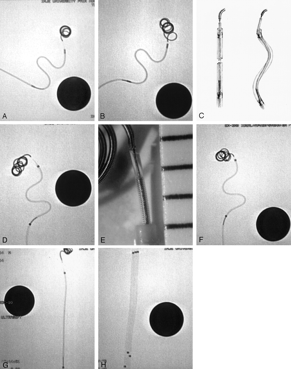
- Fig 4.
Fluoroscopic images and photograph show changes in position of coil detachment zone from catheter tip with catheter manipulations. The diameter of the black circle in the fluoroscopic images is 1 cm. A division of the ruler shown in the photograph (E) is 1 mm.
A, Fluoroscopic image shows that random catheter curve (Prowler-10) on distal 3 cm causes coil detachment zone to protrude further from catheter tip.
B, Fluoroscopic image shows marker alignment at ideal alignment in same catheter as that shown in A.
C, Schematic illustrations show effect of marker distance shortening with catheter curves. The stiff delivery wire maintains a relatively straight course within a tortuous microcatheter (right). The coil is thus more protruded than with a straight catheter (left). Catheter curves without steaming simulate vascular tortuosity.
D, Fluoroscopic image shows that steam shaping of an Excel-14 makes coil protrude more from catheter tip than with unmodified Excel-14.
E, Photograph shows that steam shaping of Excel-14 makes coil protrude more from catheter tip than with unmodified Excel-14.
F, Fluoroscopic image shows marker position at ideal alignment in same catheter.
G, Fluoroscopic image shows shortening of marker distance after ethylene oxide gas sterilization. The catheter is an Excel-14.
H, Fluoroscopic image shows various lengthening of catheters after gentle manual stretching. All catheters are Excel-14s.


Tables
Length profiles of the microcatheters tested
Excel-14* Rebar-14 Prowler-14 Excelsior FasTracker-10 Prowler-10 Proximal marker 0.59 ± 0.01 0.66 ± 0.05 1.28 ± 0.04 0.60 ± 0.03 0.62 ± 0.04 1.27 ± 0.03 (0.57 ∼ 0.60) (0.58 ∼ 0.70) (1.25 ∼ 1.36) (0.57 ∼ 0.63) (0.58 ∼ 0.65) (1.25 ∼ 1.36) Distal marker 0.61 ± 0.01 0.93 ± 0.02 1.41 ± 0.05 0.59 ± 0.03 0.61 ± 0.02 1.44 ± 0.07 (0.59 ∼ 0.62) (0.90 ∼ 0.95) (1.33 ∼ 1.47) (0.56 ∼ 0.63) (0.60 ∼ 0.62) (1.34 ∼ 1.52) Radiographically transparent zone of the catheter tip 0.80 ± 0.05 0.82 ± 0.10 0.50 ± 0.09 0.74 ± 0.04 0.79 ± 0.12 0.44 ± 0.04 (0.75 ∼ 0.88) (0.73 ∼ 0.93) (0.43 ∼ 0.65) (0.68 ∼ 0.77) (0.65 ∼ 0.88) (0.40 ∼ 0.50) Position of the coil detachment 1.50 ± 0.23 1.18 ± 0.21 1.43 ± 0.15 1.56 ± 0.27 1.33 ± 0.15 1.42 ± 0.17 zone from the catheter end with usual alignment (1.22 ∼ 1.73) (0.08 ∼ 1.29) (1.24 ∼ 1.57) (1.22 ∼ 1.80) (1.21 ∼ 1.50) (1.18 ∼ 1.57) Note.—Average (mm) ± SD (minimum ∼ maximum); usual alignment refers to the marker alignment with which non-SyngerG GDC is advanced until the proximal end of the radiopaque marker on the delivery wire is exactly distal to the proximal marker on a microcatheter.
* An Excel-14 microcatheter with a long transparent zone of the catheter tip (1.68 mm) is excluded.
In this issue


Jump to section
Related Articles
Cited By...
- No citing articles found.