
Abstract
BACKGROUND AND PURPOSE: Stent implantation alone might not be sufficient to produce definitive treatment of cerebral aneurysms. Therefore, extended experimental work is needed to improve results. We show the feasibility of using an in vitro anatomically shaped elastic model for flow evaluation before and after stent implantation.
METHODS: Based on human vascular casting, an anatomic elastic internal carotid artery model, including an aneurysm on the supraclinoid portion, was manufactured. The model was connected to a circulatory loop to simulate physiological flow. After visualization of the flow by using glass particles and laser sheet translumination, the digitally recorded data were transferred for computer analysis. Intra-saccular flow pattern changes and the vortex velocity reduction induced by the stent were investigated qualitatively and quantitatively.
RESULTS: The distal neck of the aneurysm behaved as a flow divider. Therefore, it was directly exposed to the hemodynamic stress. Inside the sac, a well-defined vortex formed and progressed along the wall toward the proximal neck. After stent implantation this pattern changed significantly; the vortex appeared more dispersed and its residence time increased. The velocity reduction was 32%. Velocity peak was observed close to the distal neck in both cases.
CONCLUSION: In vitro anatomic elastic models are feasible for flow evaluation with laser sheet translumination. In our model, stent implantation resulted in hemodynamic changes that might favor the exclusion of the aneurysm from the circulation and can prevent regrowth of the aneurysmal sac.
With the increasing role of endovascular repair of cerebral aneurysms (1), a need exists to further improve the technical capabilities. Large neck aneurysms are especially challenging. In such cases, endovascular coil or neurosurgical clip use alone has had limitations and led to a relatively high incidence of aneurysm neck remnant or regrowth (2–6). At present, stent implantation into cerebral arteries is an evolving and increasingly considered tool to reconstruct cerebral arteries diseased with aneurysms (7), especially in cases of segmental arterial diseases, such as fusiform or large neck aneurysms. Based on in vivo animal studies (8–10) and clinical experience (11), the wall reconstruction with stents of such aneurysms is usually technically feasible. However, the currently available stents alone might not be sufficient to induce permanent intra-aneurysmal thrombosis. In these cases, stent placement should be completed by supplementary procedures, such as tight coil packing (12–14) of the sac. Although arterial wall repair by using stents alone has also been reported (11, 15, 16), the improvement of the hemodynamic efficacy of stents seems to be necessary. If stent treatment of cerebral aneurysms becomes satisfying for a wider range of lesions, one could imagine a significant change in the process of the endovascular treatments, including a reduction of the amount of implant delivery, a shorter procedure time, and a better scaffold for the definitive repair of the wall defect. To improve the hemodynamic efficacy of stents and to tailor optimized stents for this purpose, further applied research is needed. The purpose of this study was to show the feasibility of an anatomic in vitro elastic model for flow evaluation before and after stent implantation and to provide a method that allows quantification of the intra-aneurysmal hemodynamics.
Methods
Aneurysm Model
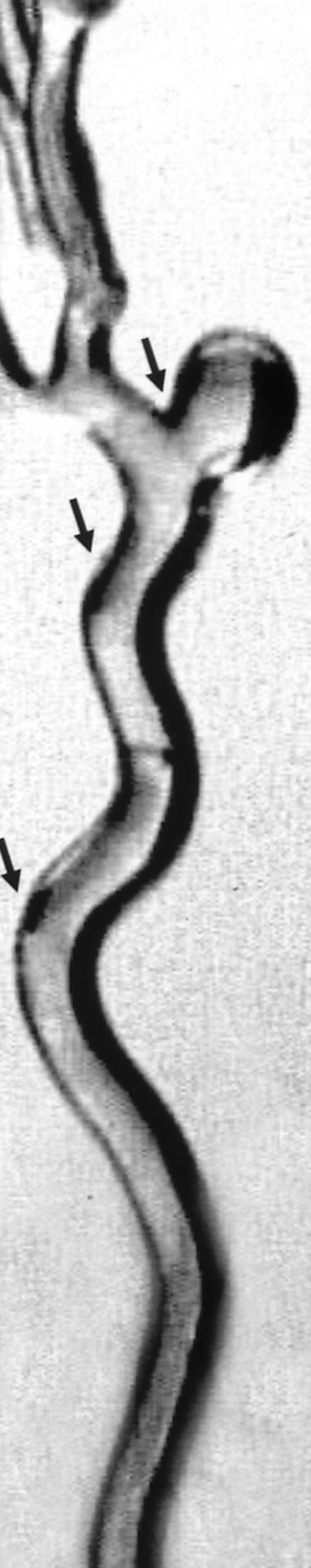
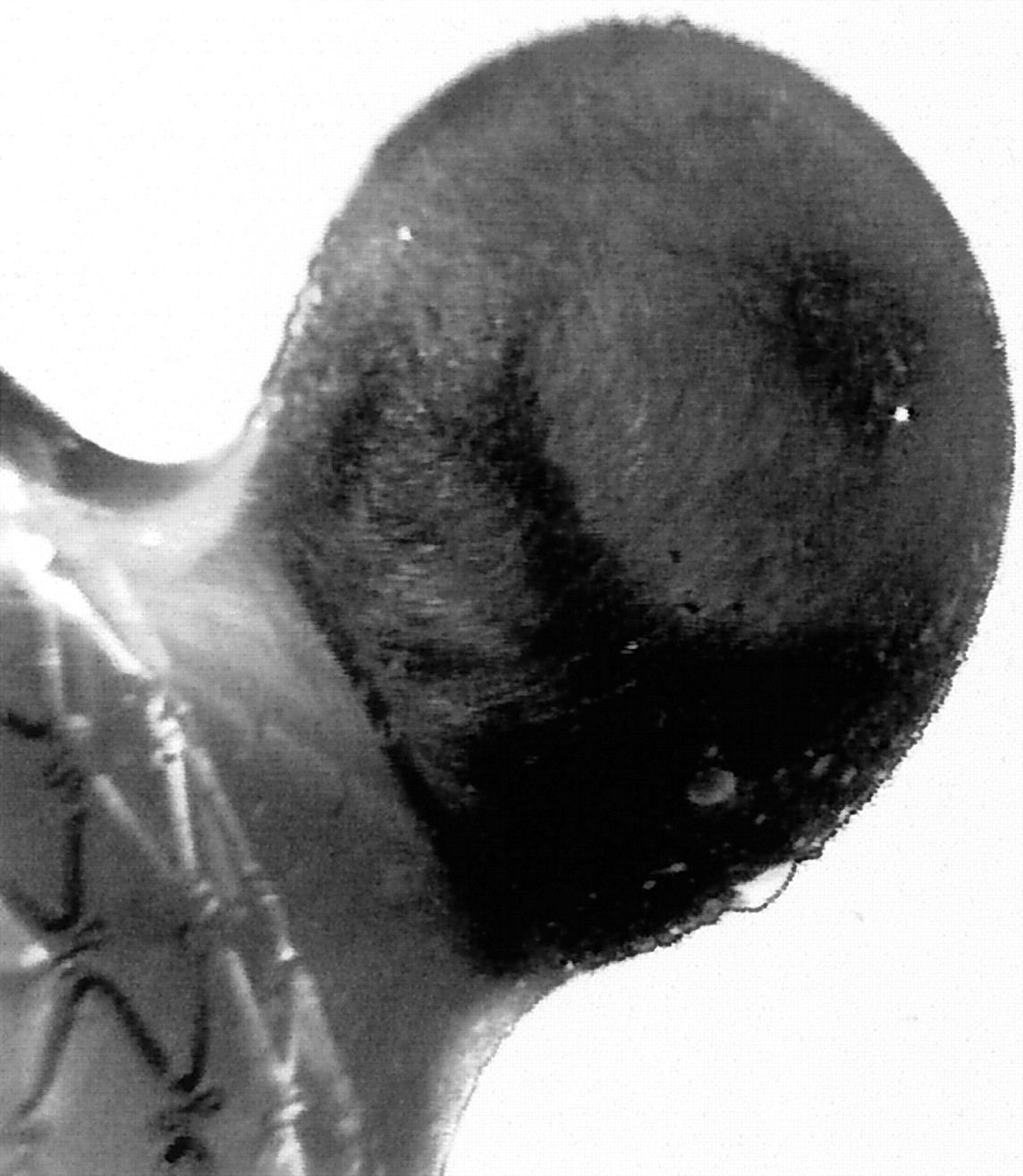
The model was manufactured by painting several layers of silicon on a rigid true-to-scale wax cast, as was described by Gailloud et al (17) (Laboratory Elastrat, Geneva, Switzerland). The tear strength of the silicon wall was retrospectively measured as 27 N/mm. The model is the replica of an internal carotid artery gained from a cadaver, modified by adding an aneurysm on the superior surface of the carotid siphon at the supraclinoid portion. The arterial lumen at the carotid siphon was 5 mm, with a largest neck size of 8 mm and a largest aneurysm diameter of 15 mm. The model is shown in Figures 1 and 2, without and with the stent, respectively. For stent placement, a commercially available intravascular stent of 6 × 18 mm was introduced.

Elastic anatomic model with physiological curves of internal carotid artery and with aneurysm located on supraclinoid segment. Arrows show increased flow intensity at these points, caused by centrifugal effect of fluid.

Lateral cross-section view of aneurysm model with implanted stent across neck.
Circulatory Loop
The main components of the experimental setup are shown in Figure 3. The flow was delivered to the aneurysm model by a pulsatile pump (GH1155; Fabre Mesurelec SA, Marseille, France), which was connected with a hydrodynamic generator, controlled by a computer signal intensity. A pressure probe (Millar F5 micro-manometer) was connected to the circulatory loop 20 cm downstream of the model and through a pressure transducer to an oscilloscope. The flow rate was regulated mechanically by a needle valve, located just before the fluid pouring into the reservoir. The loop was completed by connecting the system components with silicon tube material of 4-mm lumen diameter.

Experimental setup.
Experiments were conducted by applying 60 beats/min pulsatile flow with systolic and diastolic pressures of 145 and 90 mmHg, simulating the blood pressure of a hypertonic patient (Fig 3, oscilloscope). A mixture of 33% glycerol and 66% water was used, which is a Newtonian fluid with the viscosity of 3695 mPas at 20°C.
The mean Reynolds number was calculated based on the expression Re = ρV2r/μ = 230, where ρ = 1,087 g/cm3 is the fluid attenuation, μ = 3695 mPas is the fluid viscosity, V = Q/πr2 = 13 cm/s is the average fluid velocity, r = 3 mm is the radius of the tube, and Q = 220 mL/s is the mean volume flow, which was measured with a test tube and a chronometer.
Flow Visualization Technique
For visualizing the flow patterns and to be able to quantify the hemodynamic changes inside the sac, glass particles of 10-μm diameter (HGS, Hollow Glass Spheres; Dantec Dynamics A/S, Skovlunde, Denmark) were injected into the circulation. The particles were injected very slowly and at 0.5-m distance from the model to avoid flow disturbances inside the system. Also, because the attenuation of the microspheres was similar to that of the working fluid, the microspheres did not induce any buoyancy effect and therefore did not disturb the flow characteristics. A 454–676-nm laser sheet (Spectra-Physics Lasers, Inc., Mountain View, CA) was applied through the longitudinal symmetry plane of the aneurysm model, making the fluid visible because of the high reflective power of the particles. The visualized flow patterns were then recorded by a video camera (JVC TK 1070 E) and a 25 image/s speed digital tape recorder.
Vortex Dynamics Evaluation
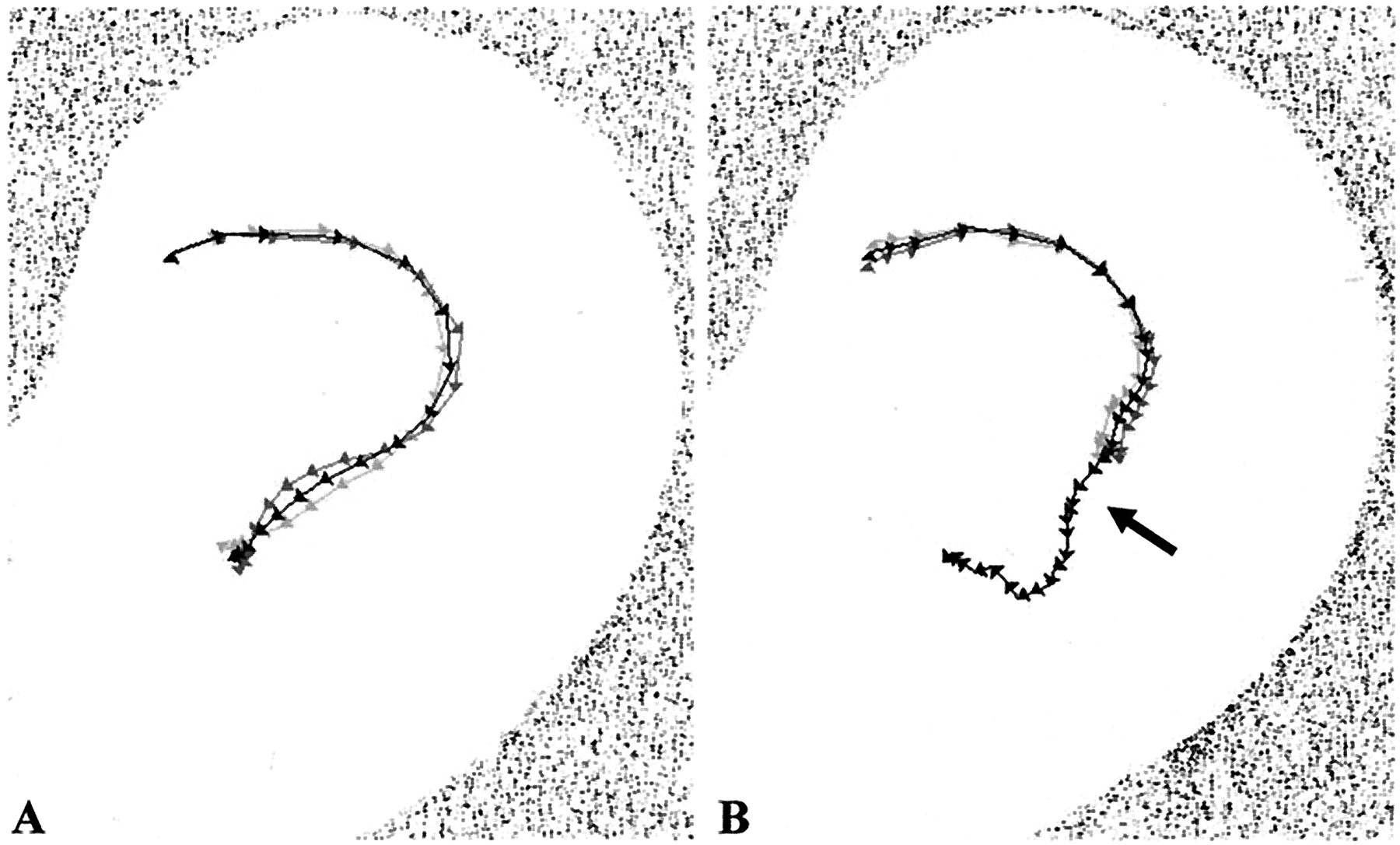
The registered video sequences were transferred for computer analysis in TIFF format at a rate of 25 images/s (Figs 4A and 5A). A Visual Basic program, including Image-Pro (Media Cybernetics) instructions, was developed to quantify the flow dynamics. Post-processing of the image data resulted in automatic subtraction of the subsequent particle clouds (Figs 4B and 5B) and identification of their centers, giving the subtracted vortex centers (SVC) (Fig 6, arrowheads). The movement of the SVC was then traced by summation of these points, providing a line. Thus, the SVC path line was created with the exact positions of the center of the subtracted vortices at 0.04-s intervals (1 s/25 images) (Fig 6). The registration was performed during two subsequent pulsation cycles providing two trajectories (Fig 6, light and dark gray lines). Based on these SVC position values, the mean position values were calculated, displaying the mean SVC path line (Fig 6, black line). Because the arrowheads on the trajectory lines represent the position (cm) of the SVC at a certain time (s), the corresponding velocity (cm/s) is easily calculated and rendered to the arrowheads. The velocity is represented by the distance between the arrowheads. In a next step, the SVC velocity values (Fig 7A) and the SVC position values (Fig 7B) were plotted versus time, making the two hemodynamic situations comparable with each other.

Gallery of images of non-stented aneurysm obtained every 0.04 s.
A, Native images.
B, Subsequent subtraction images.

Gallery of images of stented aneurysm obtained every 0.04 s.
A, Native images.
B, Subsequent subtraction images.

Trajectories of subsequent subtracted vortex advancement (SVC path line). Arrow shows flow unsteadiness due to effect of next vortex entering into cavity.
A, Non-stented model.
B, Stented model.

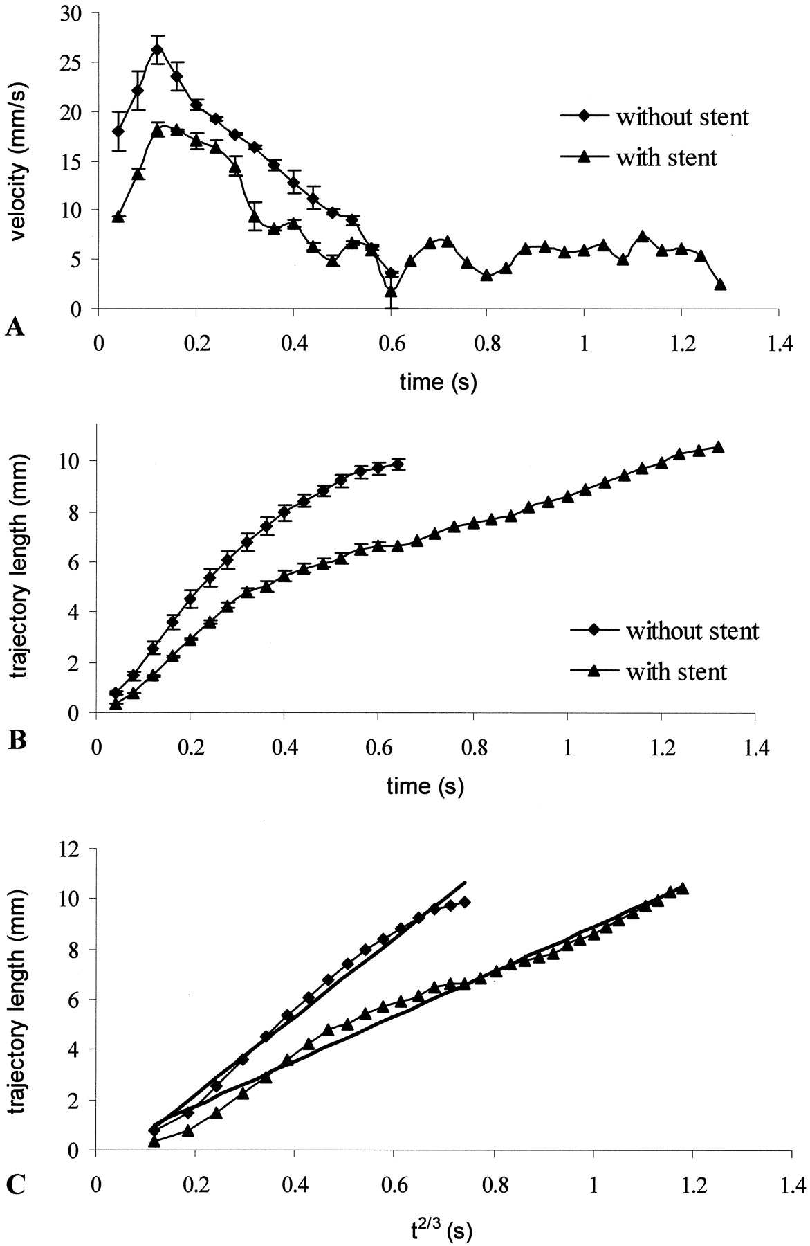
Graphs show SVC velocity and position values.
A, Direct velocity. Velocity of vortices in function of time shows pulsatile characteristics of flow.
B, Indirect velocity. Trajectory length of vortex advancement (SVC position values) in function of time represents velocity of vortices.
C, Trajectory length in function of power of time.
In addition, the flow velocity reduction (VR) after stent implantation was calculated through the formula: 
where VR is the velocity reduction (%), v̄st is the intra-saccular mean velocity after stent placement (cm/s), and v̄wst is the intra-saccular mean velocity without stent (cm/s).
Results
Aneurysm Model
The above described method of manufacturing an in vitro aneurysm model provided a transparent, thin walled structure with elastic properties. The native (without particle injection) photo about the internal carotid artery model (Fig 1) after introducing it into the circulation circuit showed the well-known physical characteristics of the flow in curves (18, 19). The flow, skewed away from the inner wall of physiological curvatures, reached maximal impact on the lumen wall at the outer curvatures, just upstream of the maximum of the curve (Fig 1, arrows). This phenomenon is also supported by the image series with glass particle injection (Fig 8A). The chosen aneurysm site was therefore in an area exposed to such a strong hemodynamic impact.

Images of models obtained every 0.12 s.
A, Non-stented model.
B, Stented model.
Flow Patterns Observed inside and Close to the Aneurysm Cavity
As described above, at the level of the aneurysm, the flow had an increased hemodynamic impact because of the centrifugal effect of the fluid. The aneurysm being implanted in this position, the main flow was split at the distal part of the aneurysm neck, behaving as a flow divider (Fig 8A). Thus, the aneurysm entry zone was at the distal neck area, whereas the exit was observed to occur at the proximal neck. The appearance of the first particles at the distal neck inside the aneurysmal cavity represents time 0 and corresponds to the first image of both series. Figure 8B illustrates the flow pattern difference after stent implantation during the same time intervals. Reconstructing the wall with a porous stent probably provides some additional areas that behave as flow dividers, redistributing the role of the distal aneurysm neck formerly acting as the only flow divider. The direct hemodynamic stress at the distal neck seems, therefore, to be reduced, which is also supported by the measured 50% VR at this area.
Figure 4 shows the intrasaccular flow characteristics without stent. The appearance of the first particles in the aneurysmal cavity represents the time 0. After divergence of the flow at the distal neck, the particle streamline enters the aneurysm and then rolls up, creating a vortex. With the progression of the vortex, the particle cloud grows with dispersion and circulates along the aneurysm wall until it is shed partially and stepwise back into the parent artery. The particle cloud is observed to reach the exit of the aneurysmal cavity at the proximal neck area, pushed by the next generation of vortices in the new systolic phase. Inside the aneurysm caged by the stent (Fig 5), this configuration is less pronounced. The vortex is more dispersed, while the vortex residence time is increased, compared with the non-stented situation. This effect of the stent is further supported by Fig 8B, which shows that not only is the distal neck no longer freely exposed to the hemodynamic stress but also the intrasaccular flow is less intensive, as indicated by the more dispersed and fewer particles at t = 0.6 s.
Quantitative Analysis of the Vortex Dynamics
For quantification, the trajectory of the vortex advancement (SVC path line) is defined (Fig 6) with the method detailed in the Vortex Dynamics Evaluation section. The arrowheads represent the exact position of the SVC at every 0.04-s interval. In the non-stented model (Fig 4), the greater distance between the arrowheads indicates higher vortex velocity. It is well seen that the velocity is the highest close to the distal neck and that it then decreases gradually in both cases. The little bend on the trajectory in the stented model (Fig 6B, arrow) represents the beginning of the next cycle. In the non-stented model, the smoother course of the streamline can be explained in that the vortex advancement is too fast and is shed out of the sac by the time the new vortex arrives. The close proximity of the two SVC path lines (dark and light gray lines) shows the reproducibility of the phenomena, which is supported by the less than SD = 1.98 mm/s maximal deviation from the mean velocity.
The SVC velocity values in function of time (Fig 7A) are shown in the direct velocity diagram, and the SVC position values in function of time (Fig 7B) are shown in the indirect velocity diagram. The former better mirrors the physiological characteristics, such as pulsatility of flow, illustrating first a velocity peak at approximately t = 0.12 s and then the slow decline until approximately t = 0.5 to 0.6 s. The stepwise appearance of the low level oscillations of the lines can be explained by the effect of flow unsteadiness on the vortex dynamics. The indirect velocity diagram (Fig 7B) reproduces steadier lines, which are easier to compare. On this graphic, the increased steepness of the line in the case of the non-stented model indicates higher velocity, thus more intensive hemodynamic impact of the flow inside the aneurysmal cavity, and the length represents the residence time of the particles.
Already, the qualitative comparison of the stented with the non-stented image galleries provides evidence of the hemodynamic influence of stent placement concerning vortex characteristics and vortex velocity, as described above. These observations are supported by the quantitative comparison of the computed SVC path lines and even more by the comparison of the velocity graphics. Although the difference between the stented and non-stented case is obvious, the significance was proved statistically by the Student t test: 2.2E-06 for the direct and 1.91E-07 for the indirect velocity curves. Moreover, we plotted the SVC position values versus the two-thirds power of time (Fig 8C), illustrating that both curves fit to a straight line with a high correlation coefficient (r2 > 0.98). Such a position versus time relationship is in close agreement with the well-known theories of vortex dynamics (20) that describe the rolling-up phenomena of a semi-infinite vortex sheet (the so-called Kaden spiral) or the vortex flow downstream of a sharp edge. The average intra-aneurysmal VR was calculated as 32% after stent implantation.
Discussion
The obvious need to apply hemodynamically more optimized stents for achieving long-term aneurysm treatment results motivated us to examine the influence of a stent on the local hemodynamics of an aneurysm. Although some results on the same subject have been presented, the reports provided only qualitative data on the flow characteristics (21, 22) or, on the contrary, gave detailed quantitative information but at the expense of applying simplified experimental conditions (23, 24). Under our laboratory conditions, we tried to reproduce, as much as possible, a physiological environment. To achieve this goal, our in vitro experiment was conducted by using an anatomically shaped model with elastic behavior of the aneurysmal wall. The necessity of an elastic wall, as opposed to a rigid wall in such models, is a subject of debate. It was shown by Liepsch et al (18) and by Löw et al (25) that the wall motion of an elastic model may alter significantly the hemodynamics; thus, false conclusions can be drawn from experiments with rigid models. However, Steiger et al (26) noted that the average flow velocity was not affected by the elasticity; only the intrasaccular pulse-wave was dampened. In another study, Perktold et al (27) also indicated that assumption of a rigid wall is correct, regarding the less distensibility of the aneurysm wall compared with the vessel wall. Still, we do not think that “less distensibility” should mean “as rigid as glass.” In our case, the pulsation of the aneurysmal wall was hardly noticeable. Scott et al (28) measured the elasticity of 16 major cerebral artery aneurysms after autopsy and found 13.5–67 × 105 dynes/cm values, which seems to be comparable with the 27 N/mm (27 × 105 dynes/cm) tear strength value of our model’s silicon wall. However, in the case of our silicon model, the aneurysm and the vessel wall possess the same elasticity values, which does not correspond to the real situation.
As far as the other parameters of our experiment, according to some suggestions (26, 29, 30), the flow was pulsatile, with the flow rate, frequency, viscosity, and Reynolds number similar to those of human flow characteristics. We applied fluid pressures mimicking hypertension, which often is associated with the presence of aneurysms (31, 32). For quantification purposes, we used a method that combined laser sheet visualization with image processing techniques.
The lateral wall aneurysm was implanted on the outer curvature of the supraclinoid portion of the internal carotid artery, providing an aneurysmal cavity more directly exposed to the flow. It is a known physical phenomenon that in curves, the velocity profile of the fluid is skewed toward the outer wall of the curve (18, 19), resulting in higher hemodynamic impact on this region. Niimi et al (33) studied the structure of flow in a similar condition through a curved vessel and with an aneurysm located on the outer circumference. They concluded that the main stream in a curvature interacts with the fluid inside the aneurysm more strongly than in aneurysms located on straight vessels because of the secondary flow induced by the curvature. Stehbens (34) conducted glass model studies of aneurysms located on straight and curved vessels and postulated that a 20-degree deflection of a distal tube induced turbulence in the aneurysm and in the distal tube at Reynolds number 1100, as opposed to the straight tube model at different Reynolds numbers below 2000.
Concerning the flow characteristics, our results came closest to the results reported by Imbesi and Kerber (22), with the aneurysm inflow zone at the distal neck, a slow moving vortex along the aneurysm periphery, and outflow at the proximal neck. Imbesi and Kerber described a significant decrease of the flow velocity after stent implantation but did not provide quantitative information. Different from our results, that the flow pattern observed by Imbesi and Kerber after stent placement revealed complete loss of the previously seen vortex flow by degrading to a residual diffuse flow toward the center of the cavity through the filaments of the stent. In our model, as opposed to their model, the swirling configuration of the flow became less pronounced, the vortex became more dispersed, and the vortex residence time increased significantly compared with the non-stented situation. However, overall, we could further on identify a vortical flow pattern (Figs 4 and 5). The difference between the two results can be explained by the different geometrical relations, including vessel curvature, aneurysm neck–volume ratio, vessel–aneurysm relationship, and stent parameters. Other flow patterns, as observed under different conditions such as changes in the flow direction during systole (35) and more pronounced flow velocity at the dome than at the neck (36), could not be reproduced with our specific model.
In summary, in our aneurysm, which was located on the outer side of a physiological curvature, a well-defined vortex structure formed at the distal neck, moved along the wall, and exited the sac at the proximal lip (Fig 4). These characteristics were significantly altered after stent implantation, although they were still clearly visible (Fig 5). The flow velocity was maximal close to the distal neck (Figs 6 and 7A) in both cases, and the mean intrasaccular vortex velocity was reduced by 32% after stent placement.
Clinical Implications of the Results
Stent implantation leads to flow reduction in aneurysmal cavities and may result in complete thrombosis of the aneurysmal sac and definitive wall repair without any additional treatment. The intrasaccular thrombus formation and the consequent exclusion of the aneurysm from the circulation is a result of successive rheological events induced by the stent. To ameliorate the results of the aneurysm treatment with stent implantation only, one should be able to measure the hemodynamic impact produced by a stent. SVC path line analysis of patient data might be possible and could be considered for this purpose. Other methods that may provide alternative possibilities to predict the chance of obtaining aneurysm thrombosis due to the treatment have been reported. Isoda et al (37) developed a tagged MR imaging method, validated with particle image velocimetry, and Sadasivan et al (38) presented a technique that allows quantification of the contrast medium washout from aneurysms by angiography.
Limitations of the Study
Based on the publications discussed above (18, 25), it is likely that we can gain more precise hemodynamic results by using an elastic model than a rigid one, although our model’s elasticity does not represent the real elastic behavior of real aneurysmal and vessel walls. The applied silicon does not possess the same elastic properties as the compliance values defined for aneurysms and arteries (28), and the elastic nature of the wall and the consequential hemodynamic influence depends on environmental factors around the aneurysm, such as the CSF and the eventually touching bones.
A second limitation is that we used a Newtonian working fluid. Although blood is a non-Newtonian fluid, in vessels larger than 0.5 mm in diameter, it is considered to behave as a Newtonian fluid (21). However, in the aneurysms, where lower shear rates (slow flow) predominate, the visco-elastic (non-Newtonian) influence may be prominent (29), resulting in lower intrasaccular velocity gradients and hence lower shear stresses (30).
Third, with our method, it was not possible to measure the velocity component parallel to and in close vicinity of the wall to calculate shear stress values. We could not measure the intrasaccular pressure either, which would represent the second component of the hemodynamic stress experienced by the wall (36) and could thus reflect the tendency for rupture, regarding certain points of the aneurysm wall.
The last limitation of our study is that the registration and analysis of the data were performed only in the symmetrical plane of the sac, which is insufficient to reproduce a real-life 3D configuration of the flow. However, we found the 2D approach to be appropriate for the purpose of comparing the stented and non-stented situations in the same positioned aneurysms.
Conclusion
The assessment of flow and flow changes induced by stent implantation using elastic in vitro silicone models is feasible for complex anatomic conditions, including curved vessel geometry and asymmetrical aneurysm shape. Digital recording of the flow, visualized by laser sheet translumination, provided a series of data suitable for image post-processing. Sequential subtracted vortex maps were used for quantification of the intra-aneurysmal flow dynamics. Stent implantation resulted in slowing down of the intra-aneurysmal vortex progression of 32%, leaving the vortex pattern to a large aspect unchanged. Repeated recordings provided reproducible data.
In the provided example, with simulation of a supraclinoid aneurysm of the internal carotid artery, stent implantation resulted in changes in the vortex characteristics and intrasaccular flow reduction of 32%, which favors aneurysm thrombosis. The 50% velocity reduction measured close to the distal neck after stent implantation and the consequent decrease of the hemodynamic stress at this region might diminish the chance of aneurysm regrowth. With these two mechanisms, endovascular treatment of an aneurysm with stent implantation can lead to complete and permanent arterial wall reconstruction, even in cases of large segmental disease of the artery.
Acknowledgments
We are thankful to the Laboratory of Elastrat (Geneva, Switzerland) for manufacturing the aneurysm models and to Christiane Dubocs (SCOM, Toulouse, France) for transferring the data for computer analysis. We also thank the Department of Mechanics, Université Paul Sabatier, Toulouse, France, for providing access to their facilities.
Footnotes
The material costs of this work were sponsored by COOK®, William Cook Europe A/S.
References
- Received May 30, 2003.
- Accepted after revision March 31, 2004.
- Copyright © American Society of Neuroradiology


