
Abstract
BACKGROUND AND PURPOSE: Aneurysm wall enhancement has been proposed as a biomarker for inflammation and instability. However, the mechanisms of aneurysm wall enhancement remain unclear. We used 7T MR imaging to determine the effect of flow in different regions of the wall.
MATERIALS AND METHODS: Twenty-three intracranial aneurysms imaged with 7T MR imaging and 3D angiography were studied with computational fluid dynamics. Local flow conditions were compared between aneurysm wall enhancement and nonenhanced regions. Aneurysm wall enhancement regions were subdivided according to their location on the aneurysm and relative to the inflow and were further compared.
RESULTS: On average, wall shear stress was lower in enhanced than in nonenhanced regions (P = .05). Aneurysm wall enhancement regions at the neck had higher wall shear stress gradients (P = .05) with lower oscillations (P = .05) than nonenhanced regions. In contrast, aneurysm wall enhancement regions at the aneurysm body had lower wall shear stress (P = .01) and wall shear stress gradients (P = .008) than nonenhanced regions. Aneurysm wall enhancement regions far from the inflow had lower wall shear stress (P = .006) than nonenhanced regions, while aneurysm wall enhancement regions close to the inflow tended to have higher wall shear stress than the nonenhanced regions, but this association was not significant.
CONCLUSIONS: Aneurysm wall enhancement regions tend to have lower wall shear stress than nonenhanced regions of the same aneurysm. Moreover, the association between flow conditions and aneurysm wall enhancement seems to depend on the location of the region on the aneurysm sac. Regions at the neck and close to the inflow tend to be exposed to higher wall shear stress and wall shear stress gradients. Regions at the body, dome, or far from the inflow tend to be exposed to uniformly low wall shear stress and have more aneurysm wall enhancement.
ABBREVIATIONS:
- AWE
- aneurysm wall enhancement
- CFD
- computational fluid dynamics
- 3DRA
- 3D rotational conventional angiography
- Gd
- gadolinium
- HR-VWI
- high-resolution vessel wall imaging
- mWSS
- mean (time-averaged) wall shear stress magnitude
- pWSS
- peak systole WSS magnitude
- WSS
- wall shear stress
High-resolution vessel wall imaging (HR-VWI) and aneurysm wall enhancement (AWE) are increasingly used to identify intracranial aneurysms with a higher risk of growth1⇓-3 and rupture.4 Aneurysms deemed “stable” on the basis of AWE may be managed conservatively and followed across time,5 whereas unstable aneurysms are treated to prevent rupture.
However, the clinical significance and exact mechanisms leading to AWE remain unclear.6 One early study of patients with SAH with multiple intracranial aneurysms showed enhancement in thick-walled regions of ruptured aneurysms, while unruptured aneurysms did not enhance.7 This finding suggested that the presence of AWE on HR-VWI may identify the culprit aneurysm in patients with multiple aneurysms and SAH. Another study observed focal AWE in association with intramural thrombus of ruptured aneurysms and suggested that AWE may be useful in identifying rupture points.8 Histopathologic analyses of specimens of intracranial aneurysms treated with microsurgical clipping have shown associations between AWE and wall thickening accompanied by atherosclerotic remodeling,9 neovascularization,10 macrophage infiltration,11 and inflammation.12,13 Several other studies have demonstrated associations between AWE and known clinical rupture risk factors: size of >7 mm,14 anterior and posterior communicating artery location,15 irregular shape,16 and PHASES score >3 (https://qxmd.com/calculate/calculator_464/phases-score).17
The subjective characterization of AWE has described patterns of enhancement as focal and circumferential. However, it is unknow why AWE does not distribute evenly within the aneurysm sac and whether this heterogeneous AWE is the result of different flow conditions within the aneurysm that ultimately translate into histologic changes.18 It is believed that flow-induced inflammation may lead to AWE. One study found lower wall shear stress (WSS) and oscillatory shear index in AWE regions compared with nonenhanced regions.19 Similarly, another study found that aneurysms with AWE were larger and had lower WSS and velocities than aneurysms without enhancement, and the AWE signal intensity was inversely correlated with WSS magnitude.20 A recent study showed that the presence of AWE was associated with low normalized WSS, size, and size ratio.21 However, several factors other than inflammation have been proposed as potential causes of increased AWE signals, in particular low-flow patterns that lead to pseudoenhancement signals in vivo.22
Our purpose was to further investigate possible associations between local flow characteristics and focal AWE with the hope of shedding light on the mechanisms responsible for wall enhancement. We used high-resolution 7T MR imaging in determining AWE and studied the local flow patterns in different areas of the aneurysm.
MATERIALS AND METHODS
Image Data
Twenty patients with 23 unruptured intracranial aneurysms were prospectively enrolled in our study of aneurysm characterization with 7T MR imaging. The MR imaging studies included a TOF-MRA and 3D T1-weighted MR imaging sequences acquired before and after intravenous injection of gadolinium (Gd) (Online Supplemental Data). Additionally, 13 patients were imaged with 3D rotational conventional angiography (3DRA) and another 4 with CTA as the standard of care and as part of their presurgical assessment if they were scheduled for an intervention. Otherwise, 3DRA or CTA or both were performed during their clinic visit if the aneurysm was not going to be treated. 3DRA, CTA, and 7T MR imaging were performed within 2 weeks as patients were recruited into the study during presurgical planning. For patients who were not treated, imaging was also completed within 2 weeks for consistency. Patient and aneurysm characteristics are summarized in the Online Supplemental Data.
Hemodynamics Modeling
Using previously described methods,23 patient-specific aneurysm models were reconstructed from the available 3D images (in order of preference, 13 from 3DRA, 4 from CTA, and 6 from 7T TOF-MRA), and computational fluid dynamics (CFD) simulations were performed by numerically solving the Navier-Stokes equations. Pulsatile inflow conditions were prescribed using waveforms measured in the internal carotid and vertebral arteries of older patients scaled with an empirical power law of the vessel area.24 Outflow boundary conditions were specified consistently with the Murray’s law. Vessel walls were approximated as rigid. Simulations were performed for 2 cardiac cycles with a time-step of 0.01 seconds, and results from the second cycle were used to characterize the local hemodynamics of the aneurysm and AWE regions.
Mapping AWE Regions
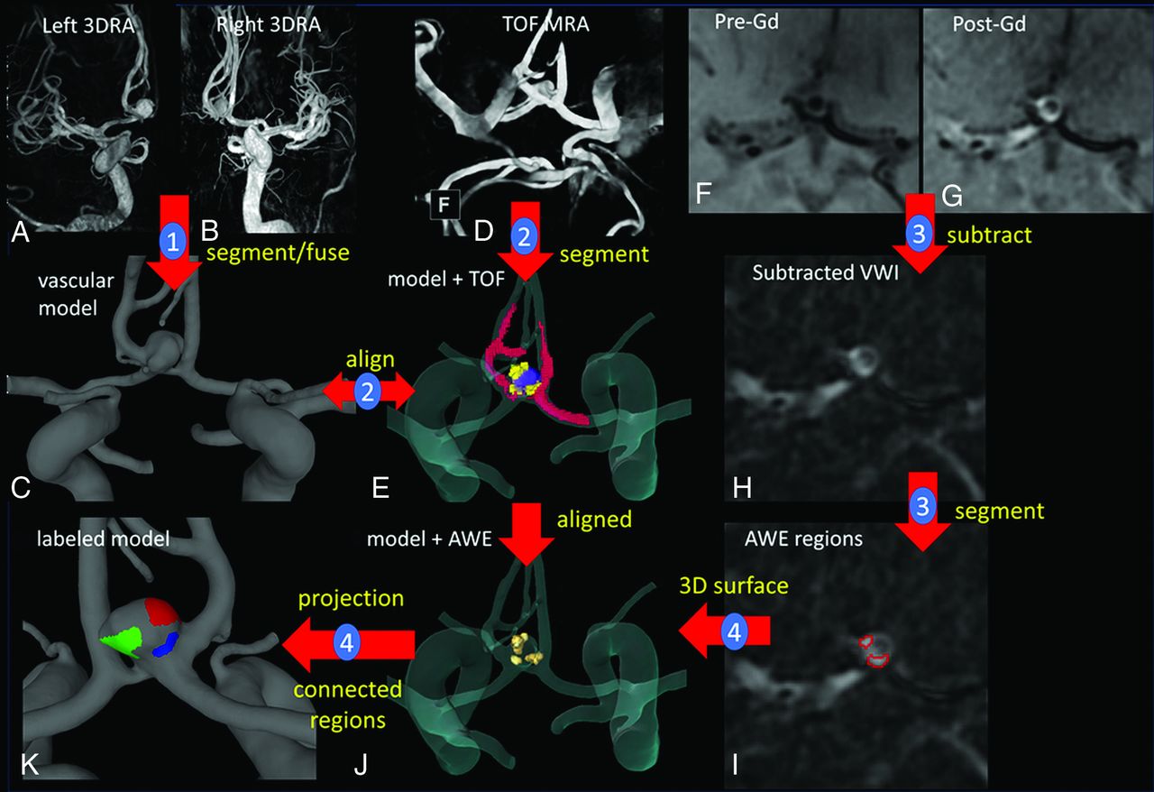
The methodology to map AWE regions to CFD models is illustrated in Fig 1. Step 1 is the construction of a vascular model from the available 3D images, as described above. Bilateral 3DRA images (Fig 1A, -B) are used to construct a model of an anterior communicating artery aneurysm (Fig 1C).25 Step 2 consists of performing a rough segmentation of the vasculature from the TOF-MRA (Fig 1D) and aligning it with the 3D model (Fig 1E, segmentation = red, model = transparent) using the image-processing software Amira Software (Thermo Fisher Scientific). In step 3, pre- and post-Gd T1-weighted images (Fig 1F, -G) are first subtracted (Fig 1H); then, AWE regions are manually segmented Fig 1I). Areas of AWE were subjectively determined by 2 teams of experienced investigators (E.A.S. and J.A.R., and S.H. and J.R.C.) and fused together by overlapping the regions. The high spatial resolution of 7T imaging allows visual determination of areas of enhancement (Fig 1F, -I) within the aneurysmal wall. In step four, 3D surfaces are recovered by extracting isosurfaces in Amira. These AWE region surfaces were thus already aligned with the 3D vascular model (Fig 1J) and were then projected onto the vascular model and used to label its surface elements as “enhanced” or “nonenhanced”. Finally, AWE regions are split into connected components and assigned different labels (colors) (Fig 1K). Note that in cases in which the vascular model was constructed from the TOF-MRA images, the AWE regions are automatically aligned and step 2 is skipped.

Illustration of methodology with the anterior communicating artery aneurysm. Step 1: model construction from 3DRAs (A–C). Step 2: rough segmentation of TOF-MRA and alignment with the vascular model (D and E). Step 3: pre- and post-Gd MR image subtraction and AWE region segmentation (F–I). Step 4: 3D-AWE region isosurface extraction, alignment, projection to the vascular model, and splitting into connected components (J and K). Models constructed from CTAs follow a similar approach, while models from TOF-MRA are automatically aligned to the Gd MR imaging series. VWI indicates vessel wall imaging.
AWE Region Characterization
The local hemodynamic environment in the aneurysm regions with and without enhancement were then quantitatively characterized by computing the region average of a number of hemodynamic variables,26 including the following: peak systole and mean (time-averaged) wall shear stress magnitude (pWSS, mWSS, respectively), oscillatory shear index, relative residence time, mean gradient oscillatory number, mean WSS divergence, and mean WSS gradient.
The location of the AWE regions on the aneurysm sac as well as with respect to the inflow stream were characterized as described below and illustrated in the Online Supplemental Data.
As in previous studies,26 the aneurysm neck was delineated by interactively selecting points on the neck and connecting them along geodesic lines (lines of minimum distance on the surface) (Online Supplemental Data). The geodesic distance to the neck was then computed for all points in the aneurysm. The aneurysm was then subdivided into 3 subregions (Online Supplemental Data) corresponding to the neck (pink), body (red), and dome (yellow).26 Then, the location of each single-connected AWE region was defined as in the neck, body, or dome, depending on the maximum percentage of overlap of the area of the AWE region and each aneurysm region. The example in the Online Supplemental Data shows 3 regions of wall enhancement (white contours) superimposed with the aneurysm regions. In this case, 1 region is located at the neck, and the other 2, at the aneurysm body.
The location of AWE regions was also characterized according to their distance to the inflow. On the basis the labels defining each region (Online Supplemental Data), close tetrahedral elements of the CFD grid were identified (Online Supplemental Data). These elements were then used to seed streamlines that pass near the AWE region. Starting at one of these seed elements, we constructed and concatenated 2 randomly selected streamlines, one in the negative velocity direction (ie, toward the inflow) and another in the positive velocity direction (ie, toward the outflow) (Online Supplemental Data). The time that it takes a particle to flow from the inflow to the seed and from the seed to the outflow was calculated. This time is given as a percentage (ie, the time from inflow to outflow is 100%). The process was repeated for 10 different seeds, and the average “time-to-inflow” was assigned to the region. AWE regions were then classified as “close” or “far” from the inflow, depending on whether their time-to-inflow was smaller or larger than the median of this variable over all AWE regions in our sample.
Data Analysis
Paired 2-sample nonparametric Wilcoxon (Mann-Whitney) tests were used to compare the means of hemodynamic variables between aneurysm regions with and without enhancement. In this case, variables were normalized with the value corresponding to the entire aneurysm, and the AWE region of each aneurysm was considered a single region (union of all connected components).
Next, single-connected AWE regions located at the neck, body, or dome were compared with the nonenhancement regions of the same aneurysm. Thus, the ratio of hemodynamic variables in each AWE region over the nonenhanced region of the same aneurysm was computed, and single-sample Wilcoxon tests were performed to test whether the ratios were significantly different from 1. Similar comparisons were also made between AWE regions located near and far from the inflow and the nonenhanced regions of the same aneurysm.
Finally, hemodynamic characteristics of AWE regions at different locations on the aneurysm (neck, body, or dome) and relative to the inflow (close, far) were compared. Thus, the ratio of variables computed in AWE regions divided by the nonenhanced region of the same aneurysm were compared using 2-sample Wilcoxon tests.
All statistical tests were performed in R statistical and computing software (http://www.r-project.org/). Differences were considered significant with P < .05 for 2-sided tests, while trends were considered marginally significant at P < .05 in corresponding 1-sided tests.
RESULTS
All 23 aneurysms studied had AWE regions. A total of 72 single-connected regions were identified in these aneurysms. Most AWE regions were located in the aneurysm body (n = 40, 56%); the remaining regions were roughly equally distributed at the dome (n = 18, 25%) and neck (n = 14, 19%). The median time-to-inflow of AWE regions was 48% with an SD of 28%.
Results of comparisons of hemodynamic characteristics of the entire AWE region against the nonenhanced region of the same aneurysm are presented in the Table. On average, the mean WSS was lower in AWE regions than in nonenhanced regions (P = .05). Additionally, the WSS divergence was negative (indicating convergence of WSS vectors) and of larger magnitude in AWE regions than in nonenhanced regions where it was positive (indicating divergence of WSS vectors) and of smaller magnitude (P = .03).
Hemodynamic characteristics (normalized with aneurysm-averaged values) of AWE and nonenhanced regionsa
Average ratios of hemodynamic variables between AWE regions at different locations over the corresponding nonenhanced region of the same aneurysm are presented in the Online Supplemental Data along with their SDs. This table includes data for regions at the neck, body, and dome, as well as regions close and far from the inflow. The P values corresponding to the comparisons of these ratios against 1 are also listed in this table where statistically significant differences are indicated with an asterisk.
AWE regions at the neck had smaller mean gradient oscillatory numbers (P = .05), higher (and negative) WSS divergence (P = .05), and higher WSS gradients (P = .05) than nonenhanced regions. In contrast, AWE regions at the body had lower peak (P = .02) and mean (P = .01) WSS and lower WSS gradients (P = .008) than nonenhanced regions. Compared with the nonenhanced regions, AWE regions at the dome also had lower WSS gradients (P = .09), but this trend only reached marginal significance. Most interesting, AWE regions far from the inflow had lower WSS (pWSS, P = .004; mWSS, P = .006) than nonenhanced regions, while AWE regions near the inflow tended to have higher WSS than nonenhanced regions, but this latter association did not reach statistical significance.
Comparisons of AWE regions at different locations on the aneurysm are presented in the Online Supplemental Data. Regions at the neck had larger WSS gradient than regions at the body (P = .002) or dome (P = .007), while the WSS gradient was not significantly different between regions in the body and dome. Additionally, AWE regions near the inflow had larger WSS (pWSS, P = .01; mWSS, P = .08) than AWE regions far from the inflow.
DISCUSSION
Previous studies have reported possible associations between AWE and low WSS.19,20 In our study, the normalized mean WSS computed over the entire AWE region was lower than that in the nonenhanced region. This result is consistent with previous reports. However, it was noticed that in most of our aneurysms, the AWE region was not single-connected. Separating them into connected components revealed that most AWE regions (56%) were located in the body of the aneurysm, with fewer regions at the neck (19%) and the dome (25%). Visualizations of the AWE regions and aneurysm flow dynamics then suggested that AWE regions at different locations could be exposed to different local flow conditions. These observations suggest that the aneurysm sac is composed of different microenvironments with different stages of histologic response to flow stressors. Wall enhancement within the aneurysm is not uniform and translates different stages of aneurysm biology on the basis of location and flow conditions.
As examples, AWE regions and flow visualizations in 4 representative aneurysms are presented in Fig 2. Aneurysm 1 has a region aligned with the inflow jet with higher WSS than the 2 other regions in the flow-recirculation regions. Note that this anterior communicating artery aneurysm has 2 daughter sacs (arrows) that colocalize with regions of AWE and low WSS. Daughter sacs or “blebs” are known sites of rupture. Aneurysm 2 has a region at the neck near the inflow, another at the neck but near the outflow, and a third at the dome. Flow conditions at these locations look qualitatively different. Aneurysm 3 has 2 regions at the neck, one near the inflow and the other near the outflow; again, WSS and flow conditions look different in these 2 regions. Aneurysm 4 has 1 region at the dome where the inflow jet impacts the wall and another near the outflow where WSS is low. These examples illustrate the complex flow conditions that shape morphologic changes and AWE regions within the aneurysm.

Sample aneurysms with multiple AWE regions at different locations on the aneurysm (row 1: AWE regions = white contours, neck = pink, body = red, dome = yellow) and relative to the inflow (rows 2 and 3), which could be exposed to different WSS (row 4).
On the basis of these observations, AWE regions were subdivided depending on their location on the aneurysm and their “time-distance” to the inflow along streamlines, to test the hypothesis that they may be exposed to different hemodynamic conditions. Our findings indicate that AWE regions at the neck near the inflow tend to be exposed to higher WSS, higher and less oscillatory WSS gradient, and higher but negative WSS divergence (indicating convergence of WSS vectors) compared with nonenhanced regions. In contrast, AWE regions at the body or dome or farther from the inflow tend to have lower WSS and lower WSS gradients (ie, more uniformly lower WSS distribution) and were more common. These opposite trends suggest that perhaps different mechanisms are involved in the processes responsible for the enhancement of regions at these different locations.
The mechanism responsible for AWE remains poorly understood. One possible mechanism is related to infiltration of Gd into the wall at locations where the endothelium became permeable. Increased endothelial permeability could also favor wall inflammation. Thus, it has been suggested that AWE is a marker of wall inflammation.10,11,18 In analyzing 25 unruptured intracranial aneurysms with 7T HR-VWI, we demonstrated a significant correlation between circumferential AWE and contrast enhancement in the parent artery.27 This suggests an underlying inflammatory/vasculopathic process in the wall of the parent vessel that ultimately may lead to aneurysm formation and growth. Endothelial dysfunction in the aneurysm and parent vessel could be the result of abnormally low WSS or oscillatory WSS conditions. The pattern of avid AWE seen in large aneurysms could be explained by the transport of Gd through the rich network of the vasa vasorum usually seen in these aneurysms.10 Finally, regions of the aneurysm wall exposed to high WSS and high WSS gradients could also result in local damage to the endothelium28 (perhaps even denudation of the endothelial layer), which may lead to wall inflammation29 and perhaps intake of Gd. Further studies will focus on better understanding of these possible mechanisms of AWE and their potential as biomarkers for aneurysm instability.
This study is limited by the small sample size and lack of follow-up data because most aneurysms were treated. Further studies with larger samples should be conducted to confirm the associations identified here. The ultra-high resolution of 7T MR imaging allowed identification of AWE in all aneurysms. This may not be feasible with lower-strength magnets, especially for aneurysms close to enhancing structures such as the cavernous sinus or in small aneurysms (≤3 mm). In these aneurysms, it may be challenging to isolate the aneurysm boundaries with 3T MR imaging. Another limitation of the study is that AWE was not objectively quantified. However, due to the small sample size, it would have been difficult to identify a specific threshold of enhancement.
CONCLUSIONS
On average, AWE regions have lower WSS than nonenhanced regions of the same aneurysm. The association between local flow conditions and AWE seems to be different for regions located at the neck and near the inflow than for regions in the aneurysm body and dome and far from the inflow. Regions in the neck and near the inflow tend to be exposed to higher WSS and WSS gradients, while regions in the body, dome, or far from the inflow tend to be exposed to uniformly low WSS. This finding suggests different mechanisms of AWE for these different regions.
Footnotes
Drs Cebral and Samaniego should be designated as co-senior authors of this article.
This work was supported by the 2019 Brain Aneurysm Research Grant from The Bee Foundation and a Pilot Research Grant from the Society of Vascular and Interventional Neurology, both granted to Dr Samaniego, and it was partially supported by the National Institutes of Health grant R01NS097457, granted to Drs Robertson and Cebral. It was conducted on an MRI instrument funded by the University of Iowa from National Institutes of Health 1S10RR028821-01.
Disclosures: Sara Hadad—RELATED: Grant: National Institutes of Health, Comments: research grant.* Fernando Mut—RELATED: Grant: National Institutes of Health*; UNRELATED: Grants/Grants Pending: National Institutes of Health, Philips Healthcare, Comments: research plans.* Edgar A. Samaniego—RELATED: Grant: Bee Foundation/Society of Vascular and Interventional Neurology, Comments: The study was sponsored by research grants from the Bee Foundation and Society of Vascular and Interventional Neurology.* Juan R. Cebral—RELATED: Grant: National Institutes of Health, Comments: research grant*; UNRELATED: Grants/Grants Pending: National Institutes of Health, Philips Healthcare, Comments: research grants.* Anne M. Robertson—RELATED: Grant: National Institutes of Health, National Institutes of Neurological Disorders and Stroke, Comments: 1R01NS097457-01*; UNRELATED: Employment: University of Pittsburgh, Comments: William Kepler Whiteford, Professor of Engineering, Associate Dean for Faculty Development; Grants/Grants Pending: National Institutes of Health, Comments: grants on cerebral aneurysms and the bladder wall, submitted proposals on cerebral aneurysms*; Travel/Accommodations/Meeting Expenses Unrelated to Activities Listed: support for travel and/or hotel at meetings, Comments: I received some support for following invited talks: 1) Plenary Speaker, Identifying Physical Causes of Failure in the Cerebral Aneurysm Wall, Computational Biomedicine Conference, Institute of Engineering and Technology on Savoy Place, London, England, September 25–27, 2019. https://www.compbiomed-conference.org/#; 2) Keynote Speaker, Identifying Physical Causes of Failure in Brain Aneurysms, 6th International Conference on Computational and Mathematical Biomedical Engineering (CMBE2019), Tohoku University, Sendai City, Japan, June 10–12, 2019. http://www.compbiomed.net/2019/; 3) Invited Speaker, Identifying Physical Causes of Failure in Brain Aneurysms, 16th Interdisciplinary Cerebrovascular Symposium (ICS 2019), Iowa City, Iowa, April 17–19, 2019, http://ics2019.engineering.uiowa.edu. *Money paid to the institution.
Indicates open access to non-subscribers at www.ajnr.org
References
- Received June 4, 2020.
- Accepted after revision September 30, 2020.
- © 2021 by American Journal of Neuroradiology


Jump to section
Related Articles
Cited By...
- No citing articles found.