
Abstract
BACKGROUND AND PURPOSE: A method is presented for high-temporal-resolution MR angiography (MRA) using a combination of undersampling strategies and a high-field (3T) scanner. Currently, the evaluation of cerebrovascular disorders involving arteriovenous shunting or retrograde flow is accomplished with conventional radiographic digital subtraction angiography, because of its high spatial and temporal resolutions. Multiphase MRA could potentially provide the same diagnostic information noninvasively, though this is technically challenging because of the inherent trade-off between signal intensity–to-noise ratio (S/N), spatial resolution, and temporal resolution in MR imaging.
METHODS: Numerical simulations addressed the choice of imaging parameters at 3T to maximize S/N and the data acquisition rate while staying within specific absorption rate limits. The increase in S/N at 3T was verified in vivo. An imaging protocol was developed with S/N, spatial resolution, and temporal resolution suitable for intracranial angiography. Partial Fourier imaging, parallel imaging, and the time-resolved echo-shared acquisition technique (TREAT) were all used to achieve sufficient undersampling.
RESULTS: In 40 volunteers and 10 patients exhibiting arteriovenous malformations or fistulas, intracranial time-resolved contrast-enhanced MRA with high acceleration at high field produced diagnostic-quality images suitable for assessment of pathologies involving arteriovenous shunting or retrograde flow. The technique provided spatial resolution of 1.1 × 1.1 × 2.5 mm and temporal resolution of 2.5 seconds/frame. The combination of several acceleration methods, each with modest acceleration, can provide a high overall acceleration without the artifacts of any one technique becoming too pronounced.
CONCLUSION: By taking advantage of the increased S/N provided by 3T magnets over conventional 1.5T magnets and converting this additional S/N into higher temporal resolution through acceleration strategies, intracranial time-resolved MRA becomes feasible.
Several approaches to MR angiography (MRA), using different contrast mechanisms, have been developed, including time-of-flight (TOF), phase contrast (PC), T2-preparation,1 and contrast-enhanced (CE) MRA. Of these techniques, all can produce high-quality static images, but only first-pass multiphase CE-MRA is capable of capturing the dynamic filling of vessels, similar to conventional radiographic digital subtraction angiography (DSA). Although CE-MRA cannot yet match the spatial and temporal resolutions of conventional radiographic DSA (∼0.1 × 0.1 mm and as many as ∼10 frames/s), CE-MRA is noninvasive, does not involve ionizing radiation, has no risk of iatrogenic stroke, and provides a true 3D dataset. Time-resolved MRA techniques have been applied to various anatomic regions with success.2-5 Previously, however, the primary goal of time-resolved MRA was to eliminate error associated with timing the arrival of contrast. As hardware and software continue to improve, noninvasive evaluation of certain pathologies where the order, direction, and rapidity of vessel filling are of clinical significance—such as with intracranial arteriovenous malformations (AVMs) and fistulas (AVFs)—is potentially within reach.6
MR imaging is flexible in that signal intensity-to-noise ratio (S/N), spatial resolution, and temporal resolution may be traded to accommodate the application. Time-resolved MRA, for example, requires high temporal resolution while maintaining sufficient S/N and spatial resolution. In recent years, much effort in the field has been devoted to developing novel acceleration, or undersampling, techniques to increase spatial and temporal resolution at the expense of S/N. These techniques can be classified as temporal or spatial undersampling, where temporal undersampling involves the interpolation of k-space samples from past and future samples at the same spatial frequency and includes techniques such as sliding window,7 keyhole,8 and time-resolved imaging of contrast kinetics (TRICKS).2 Spatial undersampling involves the interpolation of k-space samples from other acquired samples in the same timeframe and includes techniques such as partial Fourier9,10 and parallel imaging.11-14
The standard superconducting MR scanner found in today’s clinic operates at 1.5T. A new generation of 3T scanners has been introduced in recent years to take advantage of the theoretical doubling of S/N at double the field strength.15 Several groups have found success with high-field timed CE-MRA in various anatomic regions, including the intracranial vasculature.16-19 High-field imaging does not come without technical challenges, however; the radio-frequency (RF) wavelength is sufficiently short that dielectric resonance and RF penetration effects become significant, resulting in signal intensity nonuniformity.20 Off-resonance effects also become more pronounced for sequences like bSSFP (balanced steady-state free precession) that are particularly sensitive to this. Finally, the specific absorption rate (SAR) increases as the square of the increase in field strength. Even so, if the S/N boost of high-field imaging could be converted into improved temporal resolution via an undersampling technique, higher frame rate scans would be possible.
The goals of this study were to (1) determine suitable imaging parameters for time-resolved CE-MRA at 3T, (2) verify the increase in signal intensity at high field for CE-MRA, (3) develop a method for intracranial high spatial resolution timed MRA at 3T, and finally based on previous goals, (4) develop a method for undersampled time-resolved MRA at 3T. This report builds on previous reports21 by providing a pulse sequence with a higher data acquisition rate as well as further acceleration via temporal undersampling. Greater reconstructed data rates enable higher frame rates and higher spatial resolution, particularly in the through-plane dimension where intravoxel dephasing in thick partitions limits sensitivity to small vessels.
Materials and Methods
All images were acquired on 1.5- and 3T whole-body MR scanners (Sonata and Trio, Siemens Medical Solutions, Erlangen, Germany). Volunteer normal subjects and patients with either intracranial arteriovenous malformations or fistulas were recruited and consented according to the guidelines of our institutional review board.
Simulations
To find appropriate imaging parameters with respect to S/N for intracranial time-resolved MRA, simulations were performed to calculate the contrast-enhanced blood S/N, and the S/N difference of contrast-enhanced blood with respect to both nonenhanced blood and the adjacent cortical gray matter as a function of TR and flip angle, α, by using technical computing software (MATLAB, MathWorks, Natick, Mass). For the Fast Low-Angle SHot (FLASH) sequence, signal intensity, S, was taken to be the steady-state transverse magnetization in the rotating reference frame immediately after RF excitation, Mx′y′ss(t=0+)22:  1) where Mz°(B0) is the equilibrium longitudinal magnetization as a function of main magnetic field strength. Because TR ≪ T*2, T*2 decay at TE is negligible. The equilibrium longitudinal magnetization was normalized to 1 at 1.5T. At 3T, this magnetization was quadrupled, because it is theoretically proportional to the square of field strength.15 With noise being linearly proportional to field strength, the resulting S/N is also linearly proportional to field strength. Because the difference in proton density between contrast-enhanced blood and both nonenhanced blood and cortical gray matter is negligible, these differences were ignored in calculating S/N differences.
T1 values of nonenhanced blood and cortical gray matter were measured at 1.5T and 3T by using a nonselective inversion recovery gradient-echo sequence (TR = 10 seconds; TE = 3.6 milliseconds; TI = [30, 120, 300, 700, 1200, 1800, 2500, 3500] milliseconds; BW = 260 Hz/pixel; flip angle = 90°; field of view [FOV] = 250 × 250 × 5 mm; matrix = 128 × 128 × 1). A least-squares fit was applied to the longitudinal magnetization regrowth measured at each inversion time for each voxel within a region of interest placed in either the sagittal sinus or in a region of cortical gray matter. T1 values were averaged in each region of interest and then averaged again between 5 healthy volunteers. The T1 value of contrast-enhanced blood was calculated as follows23,24:  2) where T1° is the T1 of nonenhanced blood, α1 is the longitudinal relaxivity of the contrast agent (4.3 mmol−1 s−1), and C is the concentration of the contrast agent. Intra-arterial contrast agent concentration, CIA, was estimated based on the injection protocol23,24:
  3) where CIV is the injected intravenous contrast agent concentration (0.5 mol/L), Cinject is the injection volume flow rate (3 mL/s), and CO is the cardiac output, assumed to be a typical value of 5 L/min. Bolus dispersion effects were ignored.
A volunteer was imaged at 1.5 and 3T by using the FLASH sequence at combinations of TR and flip angle ranging from 2 to 5 milliseconds and 5° to 40°, respectively, to experimentally verify the relationship between these parameters at the SAR limit. The empirical data were fit according to the following approximate relationship16:  4) where ft represents transmitted RF bandwidth. At the SAR limit with constant ft, the ratio of maximum allowable flip angle at 3 to 1.5T was calculated for each TR and then compared with the value predicted by the model, which is 2. The SAR limit for the head is currently 3.2 W/kg in both normal and first level controlled modes according to FDA guidelines.
Imaging
The gadolinium-based contrast agent (Magnevist, Berlex, Wayne, NJ) was administered with a power injector (Spectris Solaris, MEDRAD, Indianola, Pa) in an antecubital vein.
CE-MRA: 1.5T versus 3T
To compare S/N and image quality at 1.5T and 3T for MR angiography, 5 volunteers (3 women and 2 men; mean age = 31 years; age range = 22–42 years) were scanned at 1.5T and again at 3T 7–14 days later. Single-channel head coils (Siemens Medical Solutions) with similar geometry were used on both 1.5T and 3T scanners to control for coil-related differences as best as possible. First, an axial dose timing scan was positioned just proximal to the carotid bifurcation to measure the time of contrast arrival to the intracranial circulation after injection (2D FLASH, TR/TE = 19.0/1.5 milliseconds; BW = 1500 Hz/pixel; flip angle = 15°; FOV = 294 × 239 mm; matrix = 128 × 64; spatial resolution = 2.3 × 3.7 mm; temporal resolution = 1 frame/s; 2 mL of contrast agent at 3 mL/s). The time of contrast arrival was subjectively defined as the peak in the signal intensity-time curve. A timed MR angiography scan was then set up in the coronal plane with coverage of the carotid arteries, circle of Willis, and cortical arteries (3D FLASH, TR/TE = 3.4/1.3 milliseconds; BW = 425 Hz/pixel; excitation pulse duration = 0.3 milliseconds; flip angle = 20°; FOV = 300 × 169 × 70 mm; matrix = 512 × 169 × 88; spatial resolution = 0.6 × 1.0 × 0.8 mm; linear ordering, 6/8 partial Fourier in all 3 dimensions; 18 mL of contrast agent at 3 mL/s). Imaging parameters and contrast dose were held fixed across examinations, independent of the size and weight of volunteers. On the basis of the time to contrast arrival, one precontrast image, serving as the subtraction mask, and 2 postcontrast images of the arterial and venous phases, respectively, were acquired.
S/N measurements were taken from the unsubtracted arterial phase images. Signal intensity was measured as the mean intensity of a region of interest placed in the cavernous segment of the internal carotid artery; noise was measured as the standard deviation of a region of interest placed in air in the same imaging section. A qualitative analysis of image quality was performed through a blinded reading by a board-certified radiologist. Images were scored on a 5-point scale (0–4) to evaluate vessel conspicuity of the Sylvian fissure (M2) branches and the more distal cortical (M4) branches of the middle cerebral arteries. In addition, images were scored for overall image quality. A statistical comparison was performed on the quantitative and qualitative analyses by using Wilcoxon signed-rank tests at a 5% significance level.
Timed CE-MRA: Partial Fourier and Parallel Imaging
As an intermediate step in the development of the time-resolved imaging technique, high-spatial-resolution images were acquired at 3T with an 8-channel phased array head coil (Siemens Medical Solutions). The 8-channel head coil provided greater localized sensitivity and enabled the use of parallel imaging. This addition of parallel imaging to the CE-MRA protocol was first validated before subsequent addition of temporal undersampling in the time-resolved imaging protocol. A dose timing scan was run first, as described previously. Angiograms were prescribed in both the coronal plane as above, and in the sagittal plane, with coverage of one whole hemisphere, including the sagittal sinus. Both triple partial Fourier (in all 3 dimensions) and in-plane generalized autocalibrating partially parallel acquisition (GRAPPA) were used to speed up acquisition (sagittal acquisition: 3D FLASH, TR/TE = 3.4/1.3 milliseconds; BW = 425 Hz/pixel; excitation pulse duration = 0.3 milliseconds; flip angle = 15°; FOV = 220 × 220 × 75 mm; matrix = 512 × 343 × 80; spatial resolution = 0.4 × 0.6 × 0.9 mm; linear ordering; 6/8 partial Fourier in all 3 dimensions; GRAPPA 2× acceleration/24 reference lines; 18 mL of contrast agent at 3 mL/s). In addition to scanning healthy volunteers (n = 5), anecdotal data were collected from patients (n = 4) exhibiting either arteriovenous malformations or fistulas.
Time-Resolved CE-MRA: Partial Fourier, Parallel Imaging, and TREAT
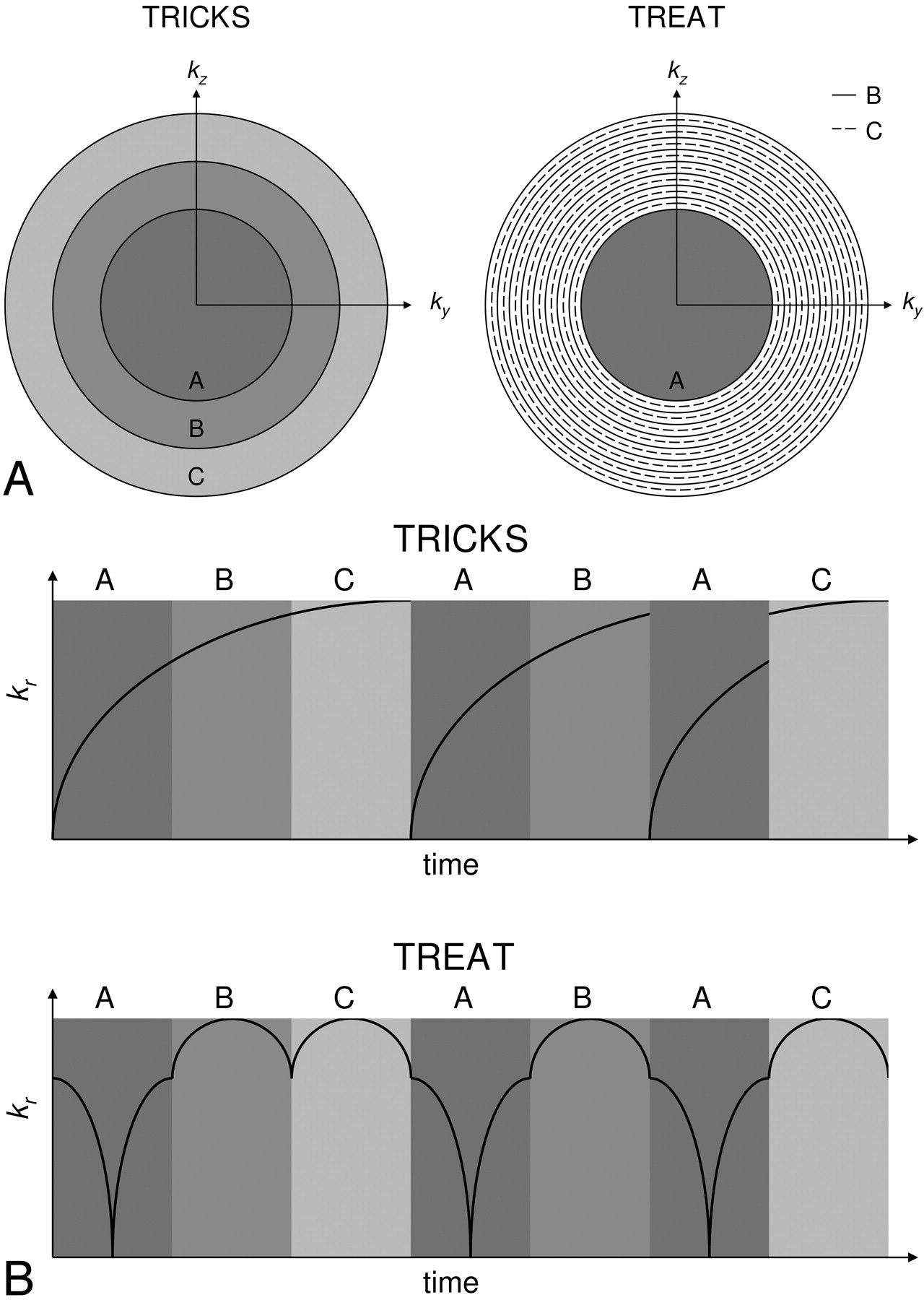
High-temporal resolution/moderate-spatial resolution images were acquired at 3T with the 8-channel head coil. No dose timing scan was necessary because the temporal resolution was greater than the normal intracranial arteriovenous transit time of approximately 3 seconds.25 The angiogram was prescribed with the same coverage as the sagittal timed MRA, similar to a lateral view conventional radiographic DSA examination with selective injection into the internal carotid. Triple partial Fourier, in-plane GRAPPA, and the time-resolved echo-shared acquisition technique (TREAT)26 were used to achieve sufficiently high temporal resolution. Because SAR limits restrict the maximum flip angle, a slightly longer excitation pulse was used to lower the transmitter bandwidth and consequently enable higher flip angles for a 0.2-millisecond time penalty in both TR and TE (3D FLASH; TR/TE = 3.2/1.3 milliseconds; BW = 600 Hz/pixel; excitation pulse duration = 0.5 milliseconds; flip = 15°; FOV = 220 × 220 × 75 mm; matrix = 192 × 192 × 30; spatial resolution = 1.1 × 1.1 × 2.5 mm; temporal resolution = 2.5 seconds/frame; 6/8 partial Fourier in all 3 dimensions; GRAPPA 2× acceleration/24 reference lines; 15 mL of contrast agent at 4 mL/s). The TREAT acquisition is diagrammed in Fig 1. For each timeframe, the central segment (A) and one of the remaining peripheral segments (B, C, D, etc.) are acquired. The acquired peripheral segment is alternated for each timeframe, such that for n segments, a given peripheral segment is acquired on every (n − 1)th frame. To fill missing data in a frame, data segments are copied from the nearest acquisition in time to the present frame. As a result, the central segment has a higher temporal sampling rate than the peripheral segments. The peripheral segments are interleaved so that each segment spans data from the boundary of the central segment to the edge of k-space. In addition, acquisition is ordered in such a way that acquisition within a segment begins and ends at the boundary between the central segment and the group of peripheral segments. Thus, large jumps between subsequent lines in k-space are avoided to suppress eddy currents and ringing artifacts.27 In addition to scanning healthy volunteers (n = 40), anecdotal data were collected from patients (n = 10) exhibiting either arteriovenous malformations or fistulas, where high-temporal frequency information is necessary to characterize the abnormality. In one patient, the time-resolved MRA was compared with a previous conventional radiographic DSA examination.

Comparison of the TRICKS and TREAT acquisition schemes. The segmentation methods are shown in panel A. In panel B, the distance of each sample from the center of k-space (kr) is plotted as a function of time to demonstrate the different ordering methods. Notice that the TREAT scheme acquires data without discontinuities in kr.
Results
Simulations
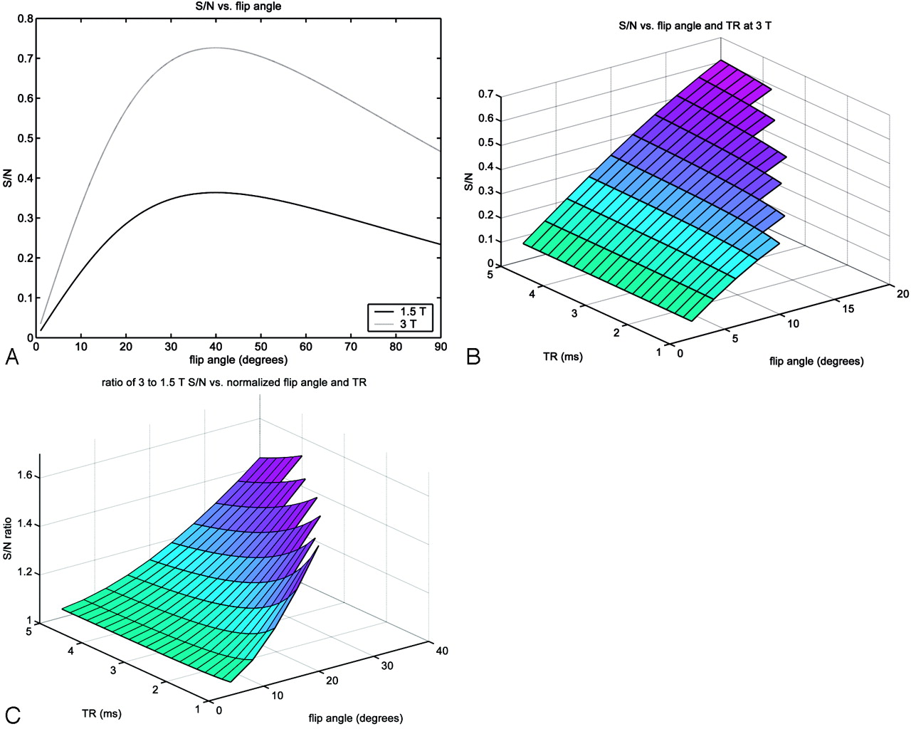
At 1.5T and 3T, the T1 values of nonenhanced blood and cortical gray matter are listed in Table 1. The plots of S/N and S/N difference were similar in shape, so just the plots of S/N are shown. Although the increase in T1 at higher field was taken into account, this was found to have a negligible effect on the S/N curves over the range of independent parameters studied. Simulated S/N versus flip angle at 1.5T and 3T is graphed in Fig 2A, demonstrating the increase in S/N at higher field. In Fig 2B, S/N is plotted as a function of both TR and flip angle at 3T for a range of values typically chosen for CE-MRA. Note that missing values at low TR and high flip angle were experimentally determined to exceed the SAR limit. The missing data define a line of maximal, constant SAR in the parameter space at which S/N is at a maximum. For this allowable range of TR and flip angle values, the acquisition is SAR-limited because the Ernst angle cannot be achieved. In this SAR-limited regime, S/N varies approximately linearly with TR and flip angle. Figure 2C is a plot of the ratio of 3T to 1.5T S/N as a function of TR and normalized flip angle, where flip angle is normalized to that which yields an equivalent amount of SAR at 1.5T. The normalization factor, averaged across each TR, was found to be 1.94 ± 0.08, in close agreement with the value of 2 predicted by the model in equation (4). The axis of normalized flip angle may be alternatively interpreted as an axis of SAR. Thus, for a given TR at the SAR limit, 3T time-resolved MRA does not achieve a full factor of 2 increase in S/N over 1.5T, but rather a factor of ∼1.6.

For enhanced intra-arterial blood: signal intensity versus flip angle at 1.5T and 3T (A), signal intensity versus flip angle and TR at 3T (B), and the ratio of 3T to 1.5T signals versus normalized flip angle and TR (C). The normalized flip angle was that which yielded an equivalent SAR at 1.5T. Missing values at high flip angles and low TRs were experimentally determined to exceed the SAR threshold.
T1 values (ms) at 1.5T and 3T for relevant intracranial contrast-enhanced MR angiography tissues
Imaging
Imaging was successful, of uniform quality, and well tolerated in all subjects. Because of little variation in image quality, images shown are representative of a typical examination and are not just examples of ideal examinations.
CE-MRA: 1.5T versus 3T
Representative images comparing 1.5T and 3T CE-MRA appear in Fig 3, where coronal maximum intensity projections (MIPs) of the mask subtraction arterial phase images are shown. Magnified views demonstrate the increased S/N at 3T by the improved conspicuity of distal cortical branches of the middle cerebral artery. Measurements taken in the cavernous internal carotid artery for each volunteer (n = 5) resulted in S/N of 34.57 ± 8.75 at 1.5T and 69.73 ± 28.27 at 3T (mean ± SD). The ratio of 3T to 1.5T S/N was 2.01, in agreement with theory. The increase in S/N at 3T was found to be statistically significant according to the Wilcoxon signed-rank test statistic (P < .05). The results of the qualitative analysis are reported in Table 2. There was a significant (P < .05) improvement in the depiction of both the M2 and M4 segments of the middle cerebral artery, and in overall image quality at 3T.

A qualitative comparison of S/N at 1.5T (A and C) and 3T (B and D) with timed coronal acquisitions is shown in these arterial phase mask subtraction MIP images. Magnified views (C and D) demonstrate better depiction of small distal middle cerebral arterial branches (circled) at 3T because of increased S/N.
Qualitative comparison of 1.5T and 3T times intracranial contrast-enhanced MR angiography
Timed CE-MRA: Partial Fourier and Parallel Imaging
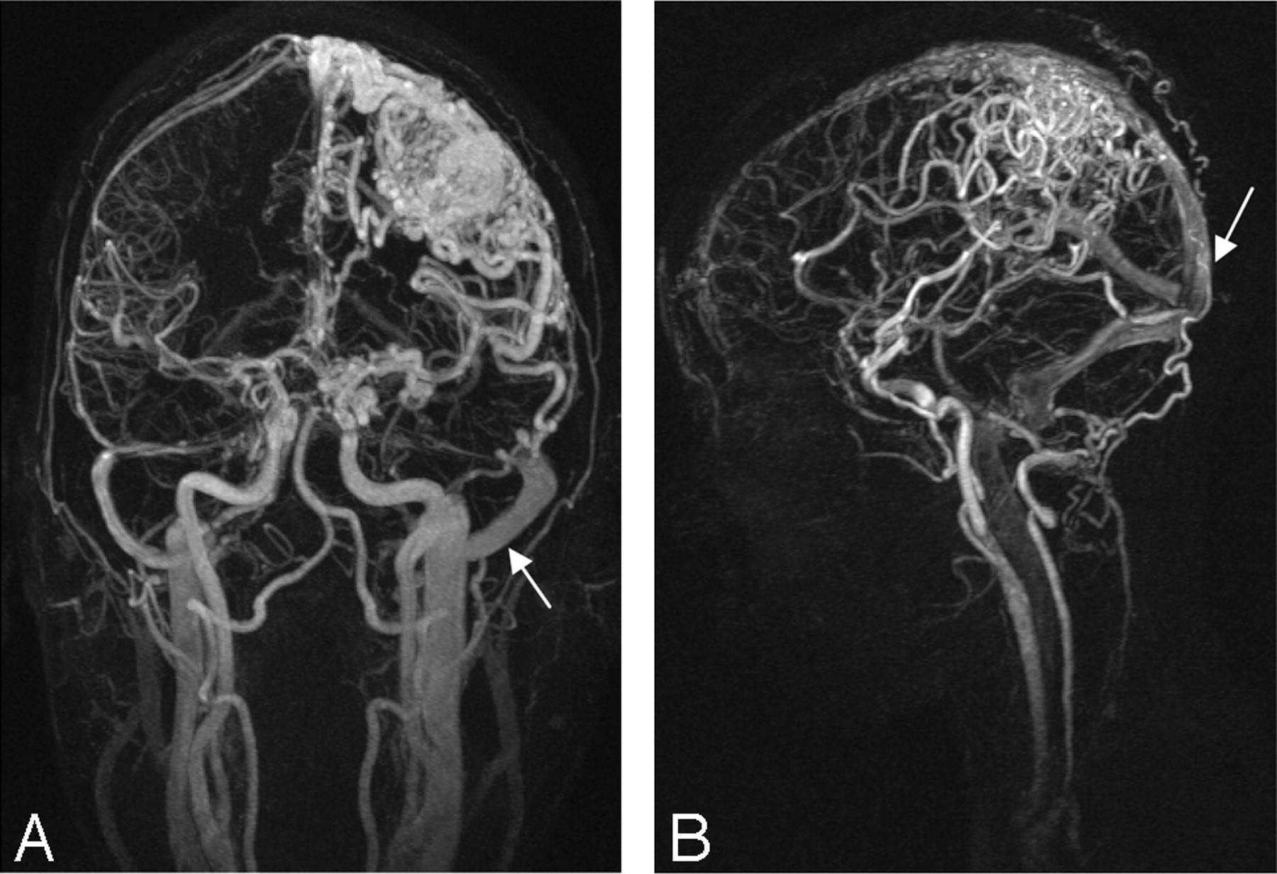
Representative 3T timed CE-MRA examinations in patients with AVMs are shown in Fig 4 in both coronal and sagittal orientations. An 8-channel head coil and parallel imaging facilitated the capture of a high-resolution arterial phase before global venous enhancement; however, rapid arteriovenous shunt surgery led to some venous contamination. No information regarding the order and direction of vessel filling may be ascertained.

Timed coronal (A) and sagittal (B) MRAs at 3T of different AVM patients are shown in these subtracted MIP images. Despite high S/N and spatial resolution, low temporal resolution makes it difficult to determine the order in which vessels fill and the direction of flow. Early venous enhancement (arrows) due to arteriovenous shunting is present and “degrades” the arterial phase.
Time-Resolved CE-MRA: Partial Fourier, Parallel Imaging, and TREAT
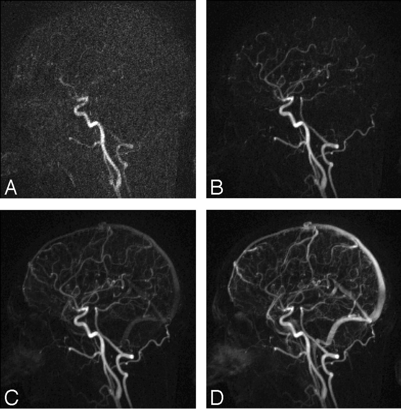
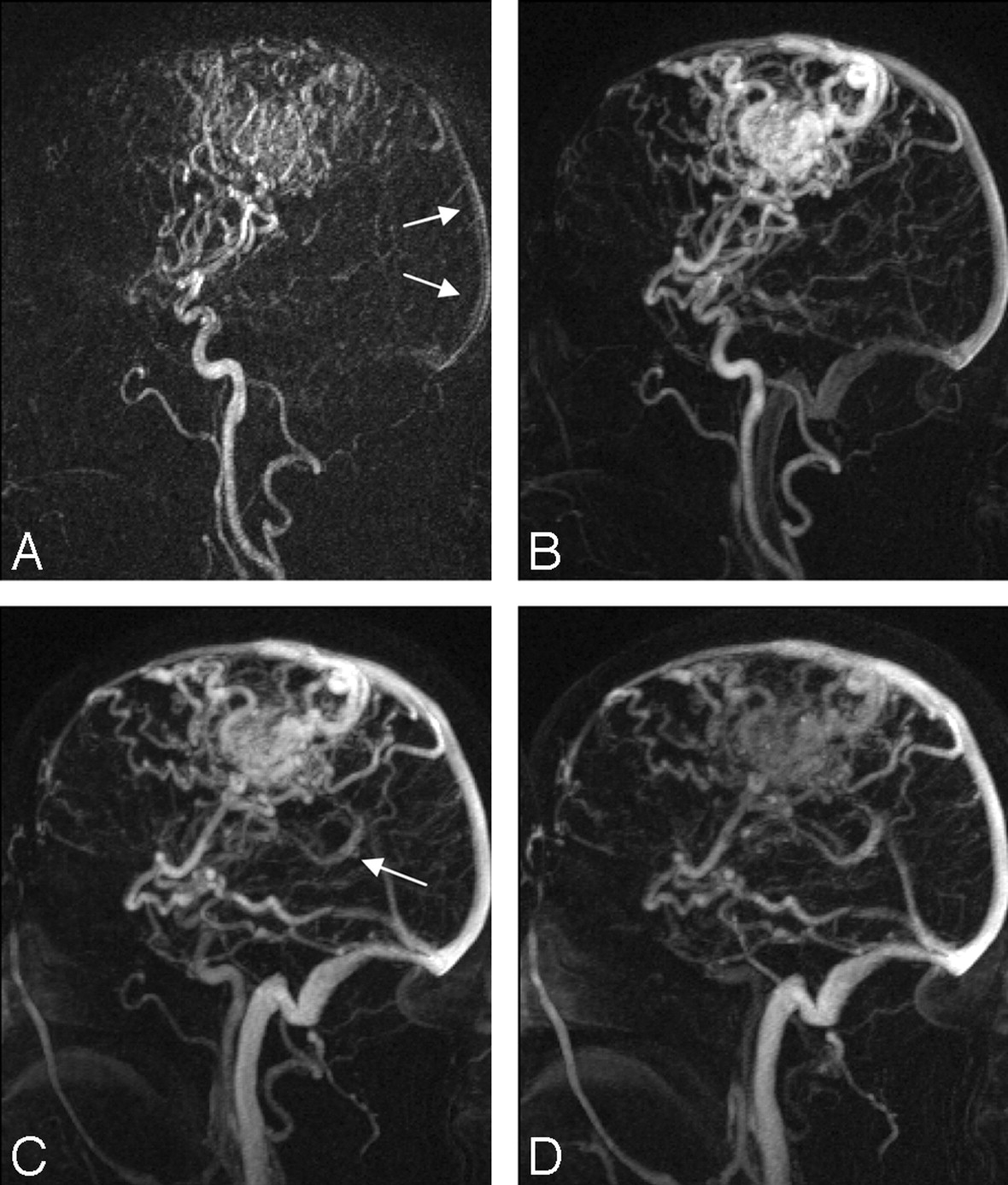
A series of consecutive timeframes from a time-resolved CE-MRA examination at 3T of a normal volunteer is presented in Fig 5. In Fig 6, the same protocol was run on a patient with an AVM. In the early arterial phase (Fig 6A), there is also very early filling of portions of the venous system. Identifying early venous shunting is critical to the diagnosis of an AVM and is possible only with multiphase techniques. Figure 7 consists of consecutive timeframes from both conventional radiographic DSA and 3T time-resolved MRA examinations of the same patient. Although the conventional radiography clearly has superior spatial and temporal resolution, the MRA still documents the dynamic passage of contrast in major vessels and identifies early venous filling. The MRA is displayed with inverse grayscale contrast to mimic conventional radiographic DSA. Temporally blurred conventional radiographic images are provided for comparison with the MR images.

Time-resolved sagittal MRA at 3T of healthy volunteer. Consecutive timeframes are shown with temporal resolution of 2.5 seconds/frame and spatial resolution of 1.0 × 1.0 × 2.5 mm.

Time-resolved sagittal MRA at 3T of an AVM patient. Consecutive MIP timeframes are shown with temporal resolution of 2.5 seconds/frame and spatial resolution of 1.0 × 1.0 × 2.5 mm. Notice subtle early venous enhancement in the sagittal sinus during the early arterial phase (A, arrows) before enhancement of the basal vein of Rosenthal (C, arrow).

Consecutive timeframes of a conventional radiographic angiogram (A–D) and a 3D MIP MR angiogram (E and F) of the same patient with an arteriovenous malformation. The MR imaging is displayed with inverse grayscale contrast for better comparison. Conventional radiographic images are temporally blurred (G and H) for comparison with the MR images. For the radiographic and MR angiograms, respectively, the spatial resolutions are 0.1 × 0.1 and 1.0 × 1.0 × 2.5 mm and the temporal resolutions are 0.3 seconds/frame and 2.5 seconds/frame, respectively.
Discussion
The simulations were intended to study the trade-off between increased S/N and increased SAR at higher field. Time-resolved CE-MRA scans are typically based on a spoiled gradient-echo sequence with a very short TR to collectively optimize S/N, spatial resolution, and temporal resolution. At 1.5T, the Ernst angle is easily achieved with a minimized TR. At 3T, however, the short TR and increased SAR place limitations on the maximum flip angle. As a result, the sequence operates in a SAR-limited regime of the parameter space, where the Ernst angle is not achieved and signal intensity is approximately linearly related to flip angle. Even so, there is still a net increase in S/N at higher field, which may be used simply to improve image contrast, or it may be “spent” via undersampling techniques to increase spatial and/or temporal resolution. By using the increase in S/N to improve temporal resolution, high-frame-rate MRA becomes feasible.
Two distinct regimes were studied in the imaging parameter space: the high TR /high flip angle regime for timed MRA, and the low TR/low flip angle regime for time-resolved MRA. In the former case, SAR is not a limiting factor, and S/N is expressed by the following relationship:  5) where V is the voxel volume, NPE is the number of phase encodes, and fr is receiver bandwidth. In the case that readout fills the majority of the TR and receiver bandwidth is minimized, fr may be substituted for TR−1. In the SAR-limited regime in which the Ernst angle cannot be achieved, S/N also becomes an approximately linear function of flip angle:
  6) According to equation (4), SAR is proportional to the bandwidth of the transmitted RF pulse. Although reducing bandwidth to decrease SAR lengthens the duration of the pulse, this may be a favorable trade-off in certain situations because TR is much greater than the pulse duration. Further research must be conducted on pulses optimized for 3T time-resolved CE-MRA. Alternatively, TR may be lengthened, necessitating higher acceleration factors.
The 1.5T versus 3T studies confirmed previous reports of improved S/N and image quality at higher field.16–18 For timed examinations, visualization of distal arterial branches beyond the circle of Willis has some important diagnostic implications. Certain disease processes have a predilection for medium and small arteries. In some patients with chronic intracranial atherosclerotic disease, plaque may simultaneously or preferentially affect the medium and small arteries. Improved distal vessel conspicuity may also prove useful in management of acute stroke patients by localizing the precise level of arterial branch occlusion. As stroke treatment evolves, it is conceivable that the specific site of embolus and degree of clot burden may play a role. For example, mechanical thrombolysis is more technically feasible for large branch occlusions (M1: proximal middle cerebral artery) compared with smaller distal branch occlusions, whereas chemical thrombolysis may not be able to penetrate a large clot burden in the M1 segment. In these instances, noninvasive determination of the exact point of occlusion may become crucial. Arterial vasospasm following acute subarachnoid hemorrhage can significantly increase patient morbidity and mortality. To date, the gold standard examination remains conventional radiographic DSA because of its ability to identify small- and medium-size arterial vasospasm. Angiographically detectable CNS vasculitis often affects medium-size arteries, some of which fall outside the purview of routine TOF-MRA. Although it is true that additional imaging slabs can be added to the current TOF technique to improve coverage, this prolongs imaging time and is potentially limited by patient motion. In addition, there is relatively poor S/N on TOF in the distal arteries that limits diagnostic accuracy. Mycotic aneurysms, while quite rare, tend to be peripheral and difficult to assess with current noninvasive techniques, often requiring conventional angiography for diagnosis. In summary, timed CE-MRA at 3T increases the conspicuity of the medium and small cerebral arteries and will potentially improve diagnostic accuracy and aid in diagnosis and treatment of selected intracranial vascular disorders.
After reviewing the choice of imaging parameters and the benefits of timed MRA at 3T, the major goal of this report is to establish the feasibility of intracranial time-resolved MRA due to the increase in S/N at higher field. Several neurovascular disorders require dynamic information for proper diagnosis. Vascular malformations involving an abnormal arteriovenous connection such as AVMs and AVFs carry a risk of hemorrhagic stroke. Because surgical treatment is directed at the feeding and draining vessels, they must be identified with a high-frame-rate angiogram following bolus injection of contrast material. The nearly instantaneous arteriovenous transit time between feeding arteries and draining veins distinguishes them from normal vessels, which have transit times on the order of 3 seconds. In cases of ischemic stroke due to occlusion of a major artery, such as the M1 segment of the middle cerebral artery (MCA), retrograde flow originating from leptomeningeal collateral vessels may supply the hypoperfused region. Knowledge of collateral flow is important in assessing perfusion, risk-stratifying treatment, and optimizing patient outcomes. Multiphase angiography allows for the differentiation of retrograde from antegrade flow. Vertebrobasilar insufficiency may result from retrograde flow in a vertebral artery due to a proximal stenosis of the ipsilateral subclavian artery, also known as subclavian steal. Retrograde flow can be identified with multiphase angiography. In each of the disorders mentioned above, time-resolved angiography can identify rapid arteriovenous transit or retrograde flow.
Although conventional radiographic DSA provides higher spatial and temporal resolution, in certain cases the noninvasive nature of MRA may justify its use over conventional radiography, particularly in screening and follow-up situations. In addition, time-resolved MRAs could become part of a comprehensive neurologic MR examination including both anatomic and functional (diffusion, perfusion, and fMRI) imaging.
To speed up acquisition and boost signal intensity in each voxel, the through-plane resolution was set to be less than the in-plane resolution. Optimizing the partition thickness is challenging because thinner partitions reduce coverage and S/N, whereas thicker partitions lower resolution, and the increased intravoxel dephasing obliterates signal intensity from small vessels. The optimal partition thickness was empirically determined to be 2.5 mm. MIPs generated in orthogonal planes are not of high diagnostic quality, but small rotations of the 3D data to separate overlapping vessels still yields sufficiently high in-plane resolution. If a high-spatial-resolution timed MRA is acquired along with a time-resolved MRA, the separate datasets may be interpreted side by side in a complementary fashion. For a given vessel, the order and direction of filling can be determined from the time-resolved scan, and its counterpart in the timed scan will have a more precisely defined shape. Another limitation of this technique is the fact that the TREAT echo-sharing scheme provides a frame rate faster than the true temporal resolution of the signal intensity. In other words, because of data sharing between frames, signal intensity in dynamic regions is blurred in time. This is an important point for clinicians to understand when assessing the timing of vessel enhancement.
As mentioned previously, undersampling techniques are necessary to trade S/N for temporal resolution in time-resolved MRA. Higher undersampling factors may be achieved if more signal intensity is available to begin with—hence the advantage of 3T magnets. The time-resolved sequence made use of several acceleration schemes, including 3D partial Fourier with zero-filling, parallel imaging with the GRAPPA reconstruction algorithm, and TREAT. By implementing a combination of techniques, each with modest acceleration factors, high acceleration was achieved overall without artifacts specific to each technique becoming too pronounced. Partial Fourier and parallel imaging with GRAPPA have been used extensively for many different applications, but the TREAT acquisition is new. The rationale behind TREAT is to use a priori information about the temporal Nyquist rate of each spatial frequency sample to optimize acquisition. Low-spatial-frequency samples require relatively faster sampling for CE-MRA. Because the sampled radial spatial frequency is a smooth function with respect to time, large jumps in the sampling of k-space are avoided, which reduces eddy currents and ringing artifacts.
Conclusions
It has been shown here, as well as in previous reports, that static intracranial CE-MRA is significantly improved at 3T compared with 1.5T. The predicted increase in S/N is realized when imaging parameters are not limited by SAR. Multiphase CE-MRA also benefits from increased signal intensity at higher field, which may be converted to higher temporal resolution via undersampling techniques. For short TR applications such as this, increased SAR at higher field limits the maximum flip angle; however, there is still a significant net increase in signal intensity. Time-resolved MRA may be a sufficient noninvasive substitute for conventional radiographic DSA in certain clinical situations.
Acknowledgments
We thank Nondas Leloudas and Sharon Coffey for help with volunteer studies, and Siemens Medical Solutions, particularly Randall Kroeker, for technical help.
Footnotes
This study was supported by the Whitaker Foundation (research grant RG-03-006).
This report was presented at the 13th annual meeting of the International Society for Magnetic Resonance in Medicine, May 7–13, 2005, Miami, Florida, and at the 43rd annual meeting of the American Society of Neuroradiology, May 21–27, 2005, Toronto, Ontario, Canada.
References
- Received June 16, 2005.
- Accepted after revision August 10, 2005.
- Copyright © American Society of Neuroradiology
In this issue


Jump to section
Related Articles
Cited By...
- Intracranial Arteriovenous Shunting: Detection with Arterial Spin-Labeling and Susceptibility-Weighted Imaging Combined
- Contrast-Enhanced Time-Resolved MRA for Follow-Up of Intracranial Aneurysms Treated with the Pipeline Embolization Device
- Noninvasive Evaluation of Cerebral Arteriovenous Malformations by 4D-MRA for Preoperative Planning and Postoperative Follow-Up in 56 Patients: Comparison with DSA and Intraoperative Findings
- Postcontrast Susceptibility-Weighted Imaging: A Novel Technique for the Detection of Arteriovenous Shunting in Vascular Malformations of the Brain
- Accuracy of Susceptibility-Weighted Imaging for the Detection of Arteriovenous Shunting in Vascular Malformations of the Brain
- A Compartment-Based Approach for the Imaging Evaluation of Tinnitus
- Prediction of Response to Chemoradiation Therapy in Squamous Cell Carcinomas of the Head and Neck Using Dynamic Contrast-Enhanced MR Imaging
- Cranial Dural Arteriovenous Fistula: Diagnosis and Classification with Time-Resolved MR Angiography at 3T
- 4D Radial Acquisition Contrast-Enhanced MR Angiography and Intracranial Arteriovenous Malformations: Quickly Approaching Digital Subtraction Angiography
- High-Resolution 3T MR Angiography of the Carotid Arteries: Comparison of Manual and Semiautomated Quantification of Stenosis
- Diagnostic Value of Multidetector-Row CT Angiography in the Evaluation of Thrombosis of the Cerebral Venous Sinuses