
Abstract
BACKGROUND AND PURPOSE: Intracranial stents have become extremely important in the endovascular management of complex intracranial aneurysms. Sizing and landing zone predictions are still very challenging steps in the procedure. Virtual stent deployment may help therapeutic planning, device choice, and hemodynamic simulations. We aimed to assess the predictability of our recently developed virtual deployment model by comparing in vivo and virtual stents implanted in a consecutive series of patients presenting with intracranial aneurysms.
MATERIALS AND METHODS: Virtual stents were implanted in patient-specific geometries of intracranial aneurysms treated with the Pipeline Embolization Device. The length and cross-section of virtual and real stents measured with conebeam CT were compared. The influence of vessel geometry modifications occurring during the intervention was analyzed.
RESULTS: The virtual deployment based on pre- and poststent implantation 3D rotational angiography overestimated (underestimated) the device length by 13% ± 11% (−9% ± 5%). These differences were highly correlated (R2 = 0.67) with the virtual-versus-real stent radius differences of −6% ± 7% (5% ± 4%) for predictions based on pre- and poststent implantation 3D rotational angiography. These mismatches were due principally to implantation concerns and vessel-shape modifications.
CONCLUSIONS: The recently proposed geometric model was shown to predict accurately the deployment of Pipeline Embolization Devices when the stent radius was well-assessed. However, unpredictable delivery manipulations and variations of vessel geometry occurring during the intervention might impact the stent implantation.
ABBREVIATIONS:
- 3DRA
- 3D rotational angiography
- FDS
- flow-diverter stent
- PED
- Pipeline Embolization Device
Conventional treatment of intracranial aneurysms consists of the external or internal obliteration of the sac by surgical or endovascular approaches, respectively. The rupture risk of the treated aneurysm is therefore stopped by preventing the blood from circulating inside the aneurysm cavity.1 The recent advent of flow-diverter stents (FDSs) has modified the treatment strategy for uncoilable aneurysms of the internal carotid artery.2⇓–4 Indeed, the low-porosity layer of FDS wires covering the neck induces intra-aneurysmal flow changes that promote progressive thrombosis and a complete exclusion of the aneurysm from the circulation.5,6 In addition, FDSs are responsible for the remodeling of the artery wall covered by the stent, preventing aneurysm regrowth as encountered in conventional treatment.3,7 It has been also shown that the thrombosed aneurysms have the capacity to fully resorb and consequently improve the symptomatology of aneurysms with mass effect.8,9 However, the mechanism of action of FDSs is still not totally understood and about 15%–25% of aneurysms remain with circulation, even after multiple-layer implantations.2,9
Various implantation concerns, including device sizing and positioning, can impact the device wall apposition negatively, the porosity at the neck level, and, consequently, the treatment outcome. For instance, insufficient stent appositions are known to be associated with vessel stenosis.10 The alteration of the porosity at the neck due to the device deformation might cause an impairment of the endothelialization of the device scaffold.11,12 The device sizing impacting the stent porosity was shown to influence the intra-aneurysmal flow modification.13
Currently, there is no clinical tool to predict these stent properties accurately and provide clinical insight to the practitioner. Furthermore, hemodynamic simulations have shown high potential in predicting intracranial aneurysm thrombosis.14⇓–16 These hemodynamic simulations require reliable and fast virtual stent-deployment methodologies.
Therefore, we have recently proposed17 a virtual stent-deployment method able to predict the local properties of braided stents (wire location, angles, porosities) and implantation parameters (stent length, landing zone) with minimal computational cost. Contrary to other methods that involve either cumbersome finite element analysis18⇓⇓–21 or complex phenomenologic constraints13,20,22⇓⇓⇓–26 to simulate the stent dynamics, the proposed model is based on a minimal number of geometric assumptions (ie, a constant interwire distance and tubular stent envelope), which were validated in vitro and in vivo for the Pipeline Embolization Device (PED; Covidien, Irvine, California).
In the present study, we aimed to extend the promising results of Bouillot et al17 to a larger cohort of patients. Therefore, we compared qualitatively and quantitatively real PED deployments with their virtual counterpart in a broad panel of aneurysm configurations.
Materials and Methods
Patient Selection and Data Imaging
The imaging data acquired during FDS implantation procedures served to measure the actual device position and the vessel geometry for further virtual stent implantation.
Patient Selection.
Patients scheduled to be treated with PED were included consecutively in this study (ethics committee authorization: 12–179, IRB-HUG, Geneva, Switzerland). Every case had an incidentally discovered or symptomatic saccular aneurysm of the anterior circulation without any sign of rupture. All patients received double antiplatelet therapy with clopidogrel and aspirin before the procedure and 6 months thereafter. Intra-arterial nimodipine was used when necessary to counter local vasospasms during the intervention.
Prestent 3DRA.
The pre-FDS implantation vessel geometry was provided by 3D rotational angiography (3DRA) performed before implantation for each case. The contrast agent was injected through the distal access catheter (Navien 5F; Covidien).
Conebeam CT of the Actual Stent.
Directly after PED implantation, a contrast-enhanced conebeam CT (VasoCT; Philips Healthcare, Best, the Netherlands) was performed to visualize the FDS apposition to the vessel wall. An intra-arterial solution of 20% contrast media and 80% saline was used to opacify the vessel lumen without hampering stent depiction. The combination of high spatial resolution (135-μm matrix voxels, n = 256) and the good contrast sensitivity of conebeam CT is particularly adapted to imaging small structures such as PED radiopaque wires.27
Poststent 3DRA.
After a pilot phase, we identified vessel geometry modifications and introduced postimplantation 3DRA to get the consistency of the vascular geometry before and after stent placement. Indeed, we have recently shown17 that tenuous variations of the vessel diameter have an important impact on the virtual stent prediction, reinforcing the importance of relying on vessel reconstruction.
Image Analysis and Virtual Stent Deployment
The arteries were segmented with an interactive watershed analysis28,29 performed on the gradient of the reconstructed 3DRA volume (146-μm matrix voxels, n = 256). This segmentation method ensured a reliable and reproducible reconstruction of the vessel geometry. In particular, the critical vessel diameter was user-independent. Subsequently, the parent vessel centerline and radius (defined as the minimal distance of the vessel boundaries from the centerline) were calculated by using VMTK30 (www.vmtk.org) and regularized to remove the short spatial scale fluctuations and minimize the effect of the intracranial aneurysm neck.17 This information was used to build the tubular envelope with a circular cross-section on which the stent wires were woven, assuming a constant interwire distance. To mimic the real implantations, we selected the distal end of each stent manually on the vessel centerline according to the actual stent position based on the conebeam CT images, and it served as input to the virtual deployment algorithm described in Bouillot et al.17
The virtual stent was computed with the weaving parameters of the actual device (nominal length/diameter of the stent with its number/width of wires) given for PED in Bouillot et al.17 In parallel, a manual threshold segmentation of the conebeam CT by using OsiriX Imaging Software (http://www.osirix-viewer.com) provided the location of the radiopaque wires of the actual stent. Finally, all these 3D data (pre-/postimplantation vessel boundaries, filaments of the virtual stents, and radiopaque wires of the real stents) were manually registered by using ParaView software (Kitware; http://paraview.org) for further comparison analysis.
Quantitative Analysis
The cross-section of the real stent envelope was measured on conebeam CT data in orthogonal planes along the centerline of the virtual stent. We analyzed its shape, assuming an elliptic cross-section as described in Bouillot et al.17 The 2 measured minor and major radii of the real stent were subsequently compared with the radius of the tubular virtual stent. Also, the length differences between real and virtual stents were estimated with the help of the ParaView software.
The variations of vessel geometries pre-/poststent implantation were quantified on the basis of the virtual stent envelopes. Their radii are representative of the minor radius of the vessel in which the influence of the intracranial aneurysm is removed. Once averaged along the virtual stent centerline, the resulting radius value provides a valuable quantification of the vessel size along the stent.
Results
Patients
Twenty patients were treated with a single-layer PED without major perioperative or delayed complications. All aneurysms were located at the internal carotid artery either in the cavernous (n = 2) or paraclinoid portion (n = 18). Eight patients underwent 3DRA post-FDS implantation for the evaluation of vessel geometry modifications occurring during the intervention and their impact on the stent deployment.
Virtual-versus-Real Stent Implantation
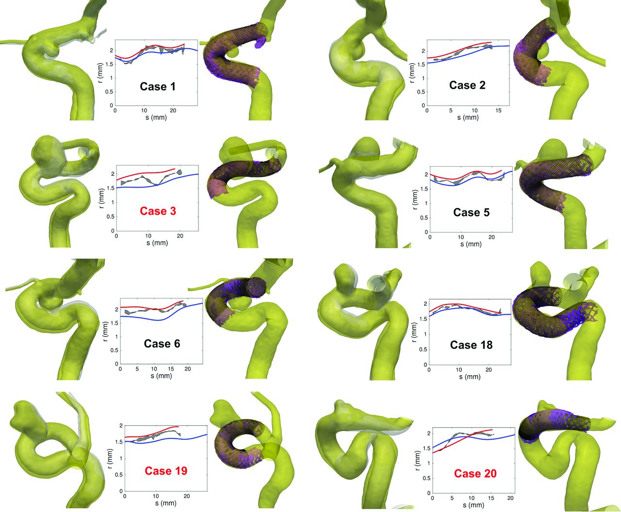
Qualitative comparisons between virtual and real stent implantations are given in Figs 1 and 2, in which the real (based on segmented conebeam CT) and virtual (based on segmented pre- and postimplantation 3DRAs) stents are superimposed on the corresponding vessel shape (pre- and poststent implantation, respectively). These figures show the good overall agreement between virtual and real stents. In general, the shape of the stent envelope was well-predicted by the virtual deployment despite the large variety of implanted vessel geometries. In particular, the regularization at the intracranial aneurysm neck guaranteed a good apposition of the stent at both sides of the neck while avoiding penetration and stent radius overestimation at the level of the aneurysm.

Visual (upper row) and quantitative (lower row) comparison between real and virtual FDS implantations in 20 patients. Upper row, The black lines are the wires of the virtual stents deployed in the 3DRA prestent geometry (gray transparent surface). The semitransparent purple surface represents the radiopaque wires of the real stents segmented from conebeam CT. Lower row, Radius (r) of the stents versus the position (s) along the centerline of the stents (the origin is taken at the distal end). The blue line represents the radius of the virtual stent based on the 3DRA prestent acquisition, while the gray area shows the minor-major radius range of the real stent cross-section based on the conebeam CT poststent acquisition. The implantations labeled in red required additional manipulation to improve the stent apposition.

Left columns, Visual comparison between the 3DRA geometries post-FDS implantations (yellow surface) and pre-FDS implantations (gray surface) for 8 patients. The post- and pre-FDS implantation vessel boundaries were manually registered by using ParaView software. Middle columns, Radius (r) of the stents versus the position (s) along the centerline of the stents (the origin is taken at the distal end). The blue (red) line represents the radius of the virtual stent based on 3DRA pre- and (post-)stent acquisitions, while the gray area shows the minor-major radius range (measured on conebeam CT) of the real stent cross-section based on conebeam CT poststent acquisition. Right columns, Visual comparison between real and virtual FDS implantations. The black lines are the wires of the virtual stents deployed in the 3DRA poststent geometry. The semitransparent purple surface represents the radiopaque wires of the real stents segmented from conebeam CT. The implantations labeled in red required additional manipulation to improve the stent apposition.
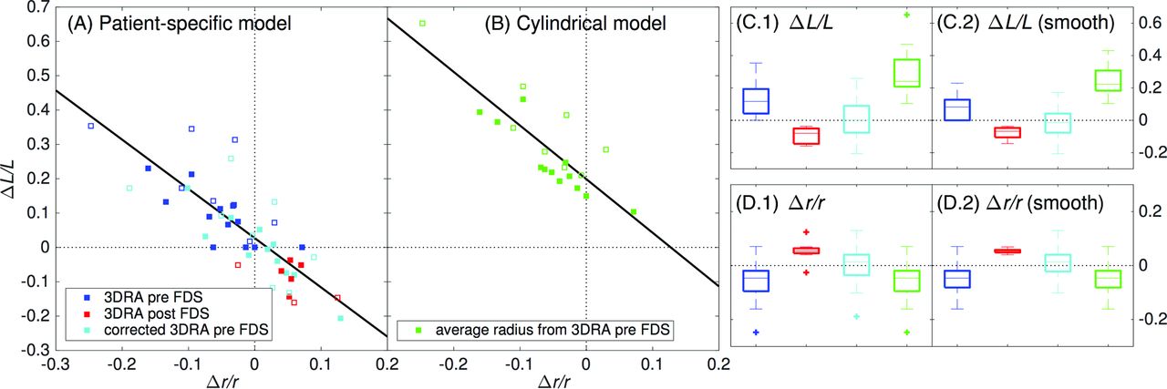
These observations were confirmed quantitatively in Figs 1⇑–3. On the one hand, a very small difference of 3% ± 1% between the minor and major radii of the real stent cross-section (ie, eccentricity of 0.25 ± 0.04) was measured, confirming the assumed circular cross-section of the virtual stent. On the other hand, the assessed virtual stent radius followed the main features of the real stent along the implanted vessel. However, the short-scale radius fluctuations were underestimated due to the stent envelope regularization process.14 Slight radial underestimations (overestimations) of −6% ± 7% (P < .05) (5% ± 4%, P < .05) were also observed in the virtual deployments based on 3DRA pre- (post-)FDS implantation. As a consequence, the predictions based on pre- (post-)3DRA acquisitions overestimated (underestimated) the FDS length by 13% ± 11% (P < .05) (−9% ± 5%, P < .05). Figure 3A shows the relation between the length differences (virtual-real) and the radial mismatches, highlighting the strong correlation between these 2 values (R2 = 0.67). The not significant intercept of 0.027 ± 0.016 (P = .11) indicated that the proposed stent deployment methodology provides an accurate prediction of the stent length when the radius of its envelope is correctly assessed. This is confirmed by correcting the virtual stent envelope radius (based on pre-FDS implantation 3DRA) by an increase of 6%, corresponding to the average radial mismatch between the virtual and real stents measured on conebeam CT data. These corrected deployments had no significant length differences, 1% ± 12% (P = .73), removing the original length shift of 13% but increasing slightly the variation range.

Virtual-versus-measured mismatch of the FDS radius [Δr / r = 2 (rvir − rmes) / (rvir + rmes)] and length [ΔL/L = 2 (Lvir − Lmes) / (Lvir + Lmes)]. A, ΔL/L versus Δr/r for the virtual deployment based on the geometric (patient-specific) model. The virtual deployments represented by the blue (red) squares are based on the vessel radius computed from segmented 3DRA pre- (post-)FDS implantation. The former were corrected by 6% (cyan boxes) to take into account the average radial difference with the measured stent radius in the virtual deployments. The straight black line represents the linear trend (R2 = 0.67) with 0.027 ± 0.016 (ΔL/L intercept) and −1.43 ± 0.20 (slope). B, ΔL/L versus Δr/r for a cylindric deployment based on the average radius of the 3DRA pre-FDS (green boxes). The straight black line represents the linear trend (R2 = 0.71) with 0.20 ± 0.02 (ΔL/L intercept) and −1.56 ± 0.23 (slope). The filled (empty) boxes correspond to the implantations without (with) additional delivery manipulation (eg, case 17 in Fig 4). C1–2 and D1–2, The virtual-versus-measured FDS radius and length mismatches, respectively. The analysis in C1 and D1 takes into account all the cases while the analysis in C2 and D2 is restricted to the 12 implantations without additional delivery manipulation. The color code is the same as that in the subsets A and B.
For comparison, the length of simplified cylindric deployments (ie, assuming a cylindric stent envelope) such as those generally provided by the stent manufacturers was also computed. Their constant stent radius was set by using the vessel radius computed from 3DRA prestent implantation averaged around the aneurysm neck (ie, the average radius of the virtual stent envelope). This cylindric model overestimated by 29% ± 13% (P < .05) the length of the stent (ie, 2.2 times more than the proposed virtual deployment [Fig 3C.1] with a much larger variation range). These cylindric-versus-real stent length differences were plotted against the radial mismatches in Fig 3B. Despite the good correlation (R2 = 0.71), the cylindric model is not able to predict the correct FDS length when its radius is well-assessed. This feature is demonstrated by the significant intercept of 0.20 ± 0.02 (P < .05), which indicates a recurring ∼20% stent length overestimation of the cylindric model.
Procedural Factors Impacting Deployment
Both the shape and the size of the vessels were modified during the procedure. On the one hand, the vessel curvature tended to decrease due to its interaction with the stent bending, as encountered, for instance, in cases 1, 5, and 20, in which this straightening led to distal or proximal registration mismatch of vessel geometries. On the other hand, the artery systematically and uniformly dilated during the implantation procedure except for case 20 (Fig 2). Quantitatively, the vessel size increased by 11% ± 7% (P < .05) between 3DRA pre- and post-FDS implantation. These dilations were not strictly located around the FDS location but affected fully the parent vessel, therefore excluding any radiopaque stent wire artifacts.
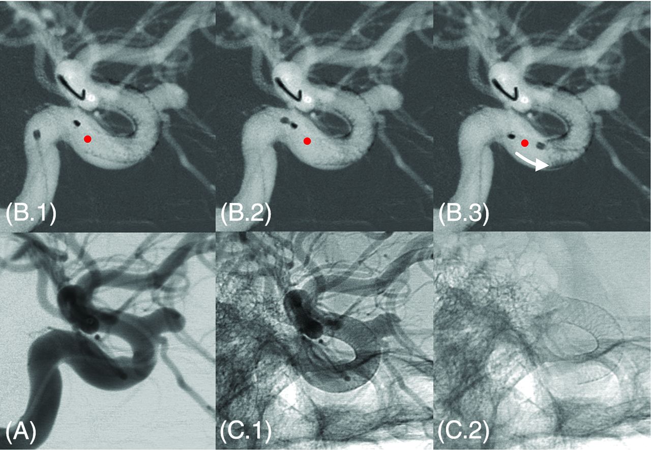
Regarding the deployment itself, images in 8 patients (labeled in red in Figs 1 and 2) showed intended manipulations of the device just after release to improve the stent apposition. These manipulations directly influenced the final state (eg, length, radius) of the device as shown in Fig 4 for case 17. These 8 cases included all the outliers of the boxplots in Fig 3C, -D and the most distant points from the linear trends in Fig 3A, -B. Therefore, the virtual-real mismatch of the stent length decreased to 8% ± 8% with a lower variation range when considering only the 12 deployments performed without additional manipulation. Furthermore, an improvement of the correlation between radius-versus-length mismatch (virtual-real) was also observed as indicated by the increase of coefficient of determination, R2 = 0.75, computed from these 12 cases.

Additional manipulation intended to improve the stent apposition in case 17. Image (A) represents the DSA preimplantation. On 3 consecutive roadmap captures (B1–3), the proximal end of the stent was pushed forward by using the tip of the microcatheter to improve the expansion of the stent within the landing zone. This manipulation induced a visible shortening of the device highlighted by the red dot (initial position of the proximal end of the stent just after release) and the white arrow in B3. C1 and C2, Unsubtracted captures just after implantation, respectively, with and without contrast agent injection.
Discussion
During the past decade, the rising use of intracranial stents and flow-diverter devices for the treatment of intracranial aneurysms has strongly stimulated biomechanical research in the simulation of stent deployment and its impact on the vasculature and hemodynamics. In particular, the device and implantation modeling is constantly refined (including the design and material properties of the device,21 its interaction with the vessel,21 the deployment procedure,19 the computational scheme20), increasing the precision of the model at the expense of the computational cost and manual intervention. However, the relevance of each model component is still debated because comparisons with in vivo stent implantations are poorly reported. In the present work, we aimed to fill this gap by comparing virtual and real FDS deployments in a cohort of patients. On the one hand, this work allowed testing the accuracy of the recently proposed deployment model for braided stents.17 On the other hand, the vessel geometry modifications occurring during the endovascular procedure and their impact on the stent implantation were also investigated.
The virtual deployment was based on some assumptions (ie, constant interwire distance and circular cross-section), which were validated in vitro and in vivo on braided stents.17 Under these assumptions and knowing PED parameters (interwire distance, wire number, and length and width assessed from manufacturer data or measured experimentally17,31), the proposed model could predict the main features of real FDSs (length, shape, filament location, porosity, and landing zone) without any free parameters. The measured low stent cross-section eccentricity confirmed the assumed tubular envelope of the virtual stent even if noisy in vivo conebeam CT prevented the characterization of the radiopaque wires of the PED as seen with in vitro measurements.17
The assessment of the virtual stent radius was shown to play an important role in the prediction accuracy. When based on pre-FDS implantation imaging, this radius was generally underestimated. On the contrary, the radii extracted from post-FDS 3DRAs were all slightly overestimated. These radial differences impacted directly the virtual stent deployment as confirmed with the high correlation between the real/virtual stent radius and length differences. This strong relation showed that the deployment model guarantees an accurate stent prediction when the radius of the stent envelope is correctly assessed as already suggested in Bouillot et al.17
The differences between real and virtual stents were partly due to the vessel geometry variations of shape and size occurring during the intervention, along with the procedure itself. In addition to the vessel straightening reported by King et al,32 a recurring vasodilation was observed after FDS implantation. These vessel modifications varied strongly from patient to patient and were not confined to the FDS surroundings. This finding indicates that the radial force of the FDS is one among other factors impacting the vessel geometry such as the mechanical impact of the catheter and vasodilator drug (nimodipine) administration. These unpredictable effects were broadly ignored in most of the previous work on virtual deployment and would require additional investigation. Furthermore, various per- and postdelivery mechanical actions performed by the operator can impact the final state of the device. For instance, the improvement of the wall apposition or proximal behavior of the stent requires additional manipulation for expanding the device as shown in Fig 4. These per- and postdelivery manipulations generally result in a compaction and therefore a shortening of the device, which are obviously not taken into account in our model.
Despite the vessel geometry variations and deployment concerns, the virtual deployment based on 3DRA pre-FDS implantation predicted the FDS length with an accuracy of about 10%. Moreover, the virtual FDS length was not biased, contrary to simplified cylindric deployments, thus ensuring accurate predictions when the stent radius is correctly assessed (ie, the vessel geometry does not vary substantially during the intervention). Most interesting, the performance of our virtual deployment was improved when the 8 cases with additional manipulation were removed from the analysis.
The minimal computational cost (only about 1 second on a laptop) and manual intervention (selection of the neck location and stent distal position) of the proposed virtual deployment are appropriate for a potential clinical application to anticipate the device positioning. Furthermore, because the underlying mathematic model is applicable to any braided stent, the virtual deployment can be extended to other types of devices. However, the circular cross-section and constant interwire distance assumptions, which have been experimentally confirmed on PEDs, should be tested with any other devices.
Conceptually, the FDS serves 2 functions in the treatment of aneurysms: It redirects blood flow and it can act as a scaffold for neointimal colonization. The reported issues associated with flow diversion concern nearly exclusively the treatment efficacy and its delayed complications (aneurysm rupture after treatment, side branch occlusion), which are basically related to hemodynamic changes, biologic factors, and medication strategies.33,34 However very few reports are dedicated to procedural complications and, in particular, the implantation and the deployment concerns of such complex devices. Due to its woven structure and its high wire density, the deployment of the FDS is not a straightforward manipulation. Zanaty et al35 concluded in a recent review that a careful manipulation of the device and a proper deployment reduced the procedure-related complications. Case 16 in Fig 5 illustrates these deployment concerns and their related delayed influence on the parent vessel. An insufficient stent apposition is visible in the inner curvature of the proximal carotid siphon immediately after implantation. Although this insufficient stent apposition is not considered an issue in this kind of procedure, one can see a vessel narrowing in the insufficient stent apposition area on the 6-month follow-up 3D angiogram. Even if the patient remained asymptomatic, the physician would have preferred to avoid such stent proximal behavior during the procedure.

A patient (case 16) with proximal insufficient stent apposition visible on conebeam CT in sagittal (A.1) and coronal (A.2) sections (white arrows). At the 6-month follow-up 3DRA, a slight narrowing is visible in the inner curvature of the internal carotid artery siphon (B.1 and B.2). This narrowing might be a bit overestimated on the 3D rendering (B.2).
Deployment issues related to the landing zone of the proximal end of the stent have already been reported by different in vivo and in vitro experiments conducted by Reymond et al.36 Particularly, they described the accordion effect, which is a protrusion of the stent inside the aneurysm associated with a too-short landing zone. In addition, they observed a transition zone of variable porosity at the neck level associated with an inhomogeneous endothelial tissue colonization of the device scaffold, which could be associated with a treatment failure. Besides, Estrade et al37 reported a case with very bad delayed outcomes related to implantation issues: A too-short landing zone and an oversized device induced a proximal conically deformed stent and a stenosis followed by immediate thromboembolic complications.
On the basis of these observations, we strongly believe that the proposed virtual deployment tool could assist the clinician in avoiding the complications described above. In practice, the deployment prediction together with its possible variability can be assessed preoperatively (ie, as soon as the 3DRA is acquired), providing additional information for optimizing the choice of the device (type, length, and diameter). Furthermore, the prediction of the proximal end of the device is essential for selecting the implantation location, ensuring an adequate landing zone. To improve the prediction accuracy and guide the practitioner perioperatively, this deployment method could be also associated with a live imaging tool. Indeed, 2D-3D registration and live imaging tracking methods could be used to locate the actual device position during the deployment to refine continuously the virtual stent prediction and the associated landing zone. Therefore, the operator could be updated on the final state of the stent while manipulating the device. Finally, our method also provides crucial information such as the filament location and neck porosity for further hemodynamic evaluation with computational fluid dynamics simulations.13⇓⇓–16
Conclusions
By comparing the predictions of the geometric model for braided stents with their in vivo counterparts in a consecutive series of patients, we emphasized the importance of the vessel radius and delivery manipulations in the model-prediction accuracy. However, the vessel geometry was shown to vary greatly during the intervention, impacting the virtual stent behavior. Independent of these implantation concerns, the proposed virtual deployment predicted the length of the PEDs with a precision of about 10%. Because the proposed stent modeling tool presents minimal computational cost and manual intervention, it has a direct clinical relevance to assist the clinician preoperatively in selecting the optimal device and anticipating its proximal position.
Footnotes
Disclosures: Pierre Bouillot—RELATED: Grant: Swiss National Science Foundation.* Zsolt Kulcsar—UNRELATED: Consultancy: Stryker Neurovascular, Medtronic, Codman; Payment for Lectures (including service on Speakers Bureaus): Penumbra. *Money paid to the institution.
This study was supported by Swiss National Science Foundation grants (SNF 32003B_160222 and SNF 320030_156813) and the Academic Health Science Center - Alternate Funding Plan (AHSC AFP) Innovation Fund.
Indicates open access to non-subscribers at www.ajnr.org
References
- Received December 23, 2015.
- Accepted after revision April 24, 2016.
- © 2016 by American Journal of Neuroradiology


Jump to section
Related Articles
Cited By...
- Implementation of computer simulation to assess flow diversion treatment outcomes: systematic review and meta-analysis
- How Flow Reduction Influences the Intracranial Aneurysm Occlusion: A Prospective 4D Phase-Contrast MRI Study
- On Flow Diversion: The Changing Landscape of Intracerebral Aneurysm Management
- Comparison of Pipeline Embolization Device Sizing Based on Conventional 2D Measurements and Virtual Simulation Using the Sim&Size Software: An Agreement Study