
Abstract
BACKGROUND AND PURPOSE: Variable head positioning in the CT gantry results in variable and inconsistent temporal bone imaging planes. Our aim was to evaluate whether an automated postprocessing algorithm or an educational intervention with postprocessing by a technologist could result in consistent temporal bone image reformations into planes referenced to the lateral semicircular canal.
MATERIALS AND METHODS: Instructions to reformat small-FOV images in planes referenced to the lateral semicircular canal were posted at 12 CT scanner consoles and e-mailed to 65 CT technologists at a single multisite institution. Automated reformatted images were also produced. The angles between the technologist- and automated-reformatted axial image planes and lateral semicircular canal planes were measured. Group differences were calculated with Mann-Whitney–Wilcoxon tests. Differences in homogeneity of variances were calculated with Fligner-Killeen tests.
RESULTS: Two hundred ten temporal bones were imaged in 4 months following the intervention. Reformats by technologists were accurate in 87% of the axial and 81% of the coronal planes, with a trend toward improvement with time. Eighty percent of incorrectly reformatted images occurred at off-site, inpatient, and emergency department scanners. The error angle was significantly lower for technologist-reformatted images (median, 4.9°) than for acquisition plane images (median, 14.6°; P = 3 × 10⁻¹⁴) or automated-reformatted images (median, 13.8°; P = 9 × 10⁻¹³). The angle error variance was significantly more homogeneous for technologist-reformatted images (P = 3 × 10⁻⁸) and automated-reformatted images (P = 1 × 10⁻⁵) than for acquisition plane images.
CONCLUSIONS: Both technologist and automated reformatting of temporal bone images resulted in significantly less imaging plane variance compared with images reformatted in the acquisition plane, but reformatting by technologists remains necessary at our institution given our preference for standardized planes referencing the lateral semicircular canals.
Patient postural constraints, patient comfort, and technologist's preference all result in variable head positioning in the CT gantry. Differences in head positioning result in associated alterations in temporal bone imaging planes when the imaging planes are based on the acquisition plane. In our practice, imaging plane variability has made it difficult to directly compare sequential temporal bone CT examinations. Moreover, imaging plane variability may interfere with pattern recognition and the ability to distinguish normal from subtle abnormal findings. However, standardization of temporal bone imaging planes can be challenging in our system of 12 CT scanners, 65 CT technologists, and a small volume of temporal bone examinations relative to other CT examinations.
Prior studies have shown that 80% of diagnostic radiology errors are perceptual: Findings are either missed or not identified as abnormal.1 For the following reasons, consistency of imaging planes through the small structures of the temporal bone is likely important in minimizing perceptual diagnostic errors. The search patterns of radiologists evolve through training.2 However, search pattern evolution may be inhibited when the imaging scene varies from examination to examination. Moreover, expert radiologists evaluate groups of features rather than individual features.3 This type of evaluation may be compromised when feature groups are inconsistently spread across a variable number of images. Finally, context and structure constrain where we search.4,5 Altering the scene and context in each imaging examination can potentially negate normal search constraints and result in a more scattered search pattern. Similarly, just as chess masters have impairment of recall when normal chess piece positions are distorted,6 it is reasonable to suspect that radiologists have impairment of normal anatomy recognition when imaging planes are distorted. If one assumes that radiologists do not have inherently better visual skills than nonradiologists,7 each of these search limitations may render an experienced neuroradiologist not much better than a novice trainee at rapidly identifying subtle temporal bone abnormalities when the imaging planes are inconsistent.
The optimal planes for temporal bone imaging have been described in one of the primary head and neck imaging textbooks: an axial plane parallel to the lateral semicircular canal and a coronal plane orthogonal to the lateral semicircular canal.8 This plane has also been described and used in research studies.9
The specific aim of this intervention and study was to evaluate whether a new automated postprocessing algorithm or a minor educational intervention with manual postprocessing procedures could result in consistent reformatting of temporal bone images into the previously published optimal planes, even across a large multisite institution.
Materials and Methods
This quality-improvement study was performed and is reported following the Revised Standards for Quality Improvement Reporting Excellence 2.0 guidelines.10
Context
Before February 13, 2018, all temporal bone helical CT examinations at our institution were manually reformatted at the CT scanner console by the CT technologist into small-FOV images of the right and left temporal bones. Axial images were reformatted in the acquisition plane, while coronal images were reformatted perpendicular to the acquisition plane. Sagittal, Stenvers, and Poschl planes were not part of our routine protocol. The axial and coronal images were, therefore, created in essentially random planes dependent on patient head positioning, not in the published optimal preferred axial plane of the lateral semicircular canal (Fig 1) or the coronal plane orthogonal to the lateral semicircular canal, as described by Curtin et al.8

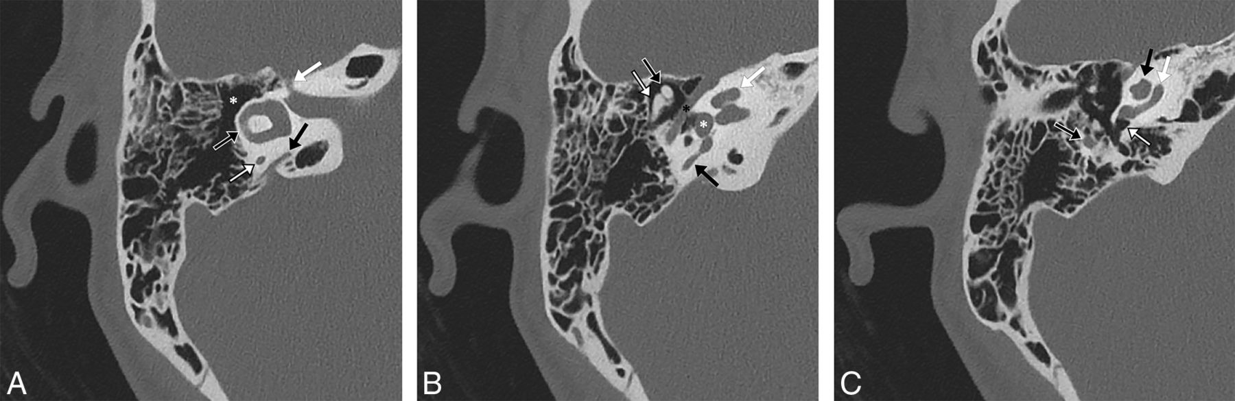
A 23-year-old woman with a normal right temporal bone. Noncontrast 0.6-mm-thick CT images in bone windows reformatted into an axial plane through the lateral semicircular canal. Major structures as seen in this plane include the following. A, at the level of the lateral semicircular canal: lateral semicircular canal (black arrow with white outline), posterior limb of the posterior semicircular canal (white arrow with black outline), vestibular aqueduct (black arrow), canal of the facial nerve labyrinthine segment (white arrow), and epitympanum/attic (asterisk). B, slightly inferior to A: the classic ice cream cone appearance of the malleus head (black arrow with white outline) and incus body (white arrow with black outline), entire length of the facial nerve tympanic segment (black asterisk), vestibule (white asterisk) at the upper aspect of the oval window, middle turn of the cochlea (white arrow), and upper limb of the posterior semicircular canal (black arrow). C, slightly inferior to B: the proximal aspect of the facial nerve mastoid segment (black arrow with white outline), round window niche (white arrow with black outline), basal turn of the cochlea (white arrow), and lower portions of the apical and middle turns of the cochlea (black arrow).
Intervention
On February 13, 2018, an instruction form (Temporal Bone Basic Multiplanar Reformation Guides, On-line Appendix) was posted at all CT scanner consoles and e-mailed to all 65 CT technologists at our institution. The instruction form described the following process for reformatting small-FOV axial images in the plane of the lateral semicircular canal, performed separately for the right and left temporal bones: 1) Locate the sagittal reformatted images on the console; 2) optimize windowing on the console so that the bony structures can be visualized; 3) identify the anterior and posterior limbs of the lateral semicircular canal on the sagittal images; 4) set the plane for the reformatted axial images so that it intersects both the anterior and posterior limbs of the lateral semicircular canal; and 5) reformat the axial images. The form then instructs the technologist to create coronal images in the same FOV in a plane orthogonal to the axial images.
In collaboration with 2 senior neuroradiologists who have >50 years of combined experience and in collaboration with a lead CT technologist with >15 years of experience, the reformatting process and instruction form were developed by a neuroradiology trainee. All temporal bone CT examinations were reviewed for adequacy of the reformatted image planes on a biweekly basis. Any errors by the technologist in choosing the reformat planes were reviewed with the performing technologist. Any technologist who did not attempt to follow the process was instructed to follow the process for all future examinations.
Measures
Each CT examination was reviewed to evaluate the CT technologist's compliance with the process and the CT technologist's success in generating the appropriate imaging planes. Axial plane images were verified to be in the plane of the lateral semicircular canal. Coronal plane images were verified by a radiologist to be perpendicular to the axial plane using electronic cross-reference lines on the PACS workstation. The lead technologist reviewed with the performing technologist any examination that was not performed correctly to ensure improvement with time.
The difference in the angle between the axial reformat plane and the plane of the lateral semicircular canal was measured by the neuroradiology trainee and confirmed as accurate by the senior neuroradiologist. This angle difference is hereafter termed the “error angle.” The error angle was measured by generating sagittal images and then using an electronic angle-measurement tool, drawing a first line along the dashed axial image cross-reference line followed by a second line through the anterior and posterior limbs of the lateral semicircular canal (Fig 2). Sagittal images were generated and angles were measured with the postprocessing software of our department (syngo.via; Siemens, Erlangen, Germany).

A 55-year-old woman with a normal left temporal bone. Sagittal noncontrast CT images in bone windows at the same location demonstrate the method of measuring the axial plane error angle. A, The angle between a line drawn by a radiologist at a PACS workstation through the anterior and posterior limbs of the lateral semicircular canal and a line drawn parallel to the plane chosen by the automation software (dotted line), which, in this case, is very close to the acquisition plane, is 16°. B, The angle between a line drawn by a radiologist at a PACS workstation through the anterior and posterior limbs of the lateral semicircular canal and a line drawn parallel to the plane selected by the technologist (dotted line) at the CT console is 4°.
Analysis
To determine an appropriate sample size, we measured the error angle for each of the 20 consecutive temporal bones (10 CT examinations) imaged immediately before the intervention. To enable a power calculation, we assumed that an error angle of up to 5° would result in a reasonable viewing plane. The sample size needed to detect an angle of at least 6° difference, with a known SD of 8.96° in the 20 temporal bones imaged before the intervention, a significance level of .05, and a power of 0.80, was calculated to be 36 in each group for a 2-sample t test. Because nonparametric analyses were planned due to potential between-group differences in variance, the estimated necessary sample size was increased to 40.
The error angle was thus measured for the 40 consecutive postintervention CT examinations (80 temporal bones) for which axial reformats were correctly performed and for which postprocessing could be performed. In addition, reformatted images of these 80 temporal bones were created with the automated temporal bone multiplanar reformatting module available with the postprocessing software of our department (syngo.via), and the error angle was separately measured for these reformatted images. The error angle was also measured for the 40 consecutive temporal bone CT examinations (80 temporal bones) performed immediately before the intervention. The preintervention and postintervention groups had no overlapping subjects. The right and left temporal bones of a single subject were considered independently because the head is often not positioned straight within the gantry, which would inherently result in different angle errors and because the right and left sides were processed independently to achieve the optimal imaging plane for each temporal bone.
Statistical significance was set at .05. Median angle error measurements were compared between the set of subjects in the preintervention group and the separate set of subjects in the postintervention group with Mann-Whitney U tests. Postintervention technologist-reformatted and automated-reformatted median angle error measurements were compared between the same set of subjects in the postintervention group with paired Wilcoxon signed rank tests. Differences in angle error homogeneity of variances between the preintervention and postintervention angle error and between the postintervention technologist-reformatted and automated-reformatted angle error were calculated with Fligner-Killeen tests. Boxplots were created to provide visual comparison of the angle errors by group. All statistics were performed with R statistical and computing software, Version 3.5.0 (http://www.r-project.org/).
Ethical Considerations
The retrospective review of medical records, including imaging examinations, was approved by our institutional review board with a waiver of informed consent and was performed in compliance with the Health Insurance Portability and Accountability Act.
Results
During the 16 weeks (4 months) immediately following the intervention, a total of 105 temporal bone CT examinations were performed, for a total of 210 temporal bones imaged at our institution. A total of 183 (87%) axial reformats were correctly created in the plane of the lateral semicircular canal, and a total of 171 (81%) coronal reformats were correctly created in the plane perpendicular to the lateral semicircular canal. The percentage of reformats correctly generated trended higher across time (Table). Fifty-three of the 66 (80%) incorrectly reformatted images occurred at off-site, inpatient, and emergency department scanners as opposed to hospital-based outpatient scanners.
Results of reformatting by a technologist
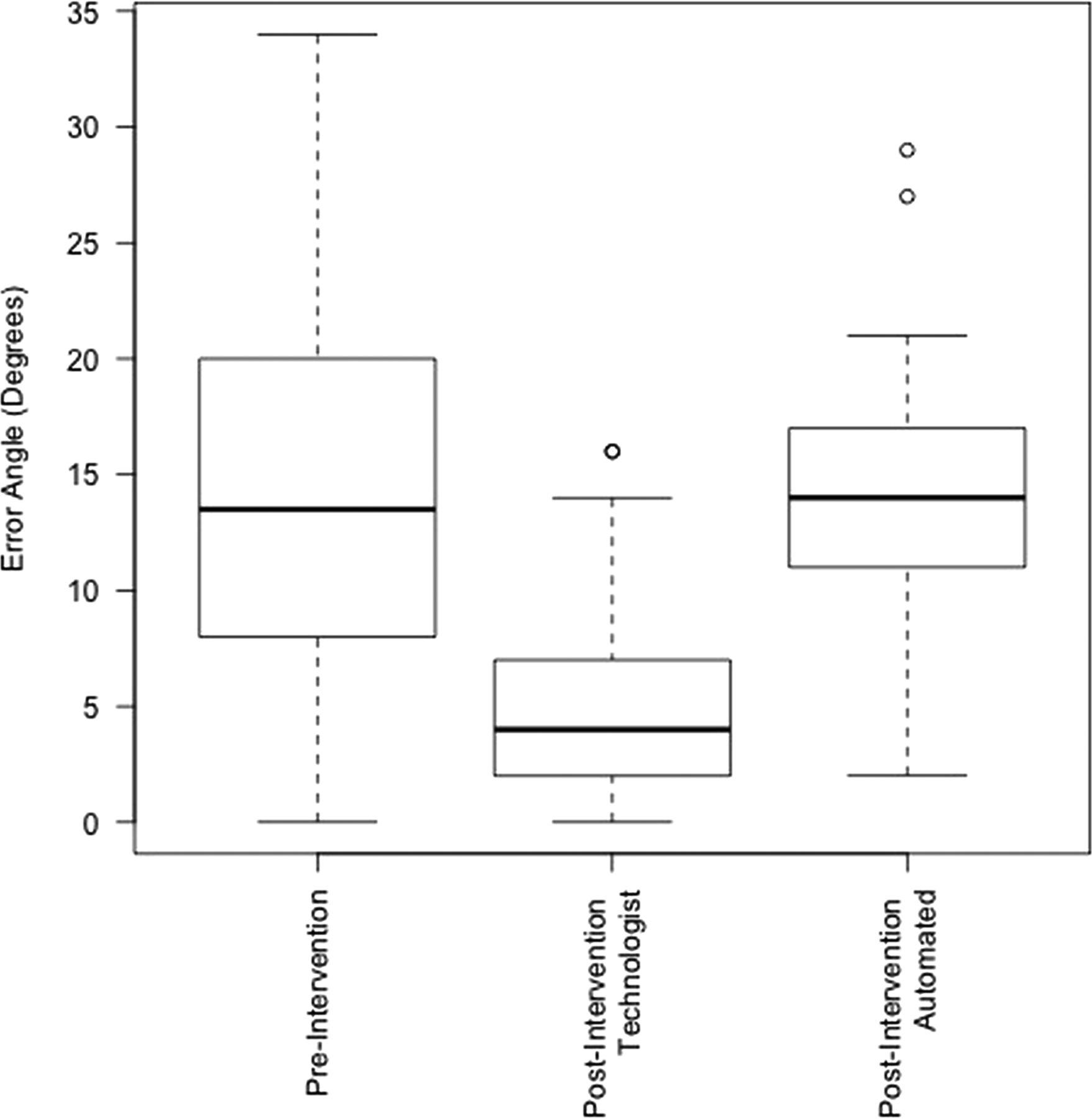
The mean error angle for the 80 temporal bones imaged immediately before the intervention was 14.6° ± 8.7° with a median of 13.5°. The mean error angle for the 80 temporal bones imaged immediately following the intervention and reformatted by the CT technologists was 4.9° ± 3.8°, with a median of 4°. The mean error angle for the 80 temporal bones imaged immediately following the intervention and reformatted with the automated tool was 13.8° ± 4.9°, with a median of 14°. Boxplots are provided in Fig 3 for visual comparison of these results.

Boxplots depicting the difference in angles between the plane of the lateral semicircular canal and the plane of the temporal bone images in the preintervention group (image plane = acquisition plane), postintervention technologist group (image plane = plane as reformatted by a technologist in the clinical setting), and postintervention automated group (image plane = reformatted by commercially available syngo.via software).
The angle error was significantly lower for technologist-reformatted axial images than for axial images in the acquisition plane (W = 5419.5, P = 3 × 10⁻¹⁴). The angle error was also significantly lower for technologist-reformatted axial images than for images reformatted with the automation software (V = 118, P = 9 × 10⁻¹³).
The angle error variance was significantly more homogeneous for technologist-reformatted axial images than for axial images in the acquisition plane (χ2 = 31, df = 1, P = 3 × 10⁻⁸) as well as for automated-reformatted axial images than for axial images in the acquisition plane (χ2 = 19.2, df = 1, P = 1 × 10⁻⁵). However, the angle error homogeneity of variance was not significantly different for technologist-reformatted axial images versus images reformatted with the automation software (χ2 = 2.7, df = 1, P = .099).
There were no unexpected benefits, problems, or failures.
Discussion
This study demonstrates that there is significantly more variance in temporal bone imaging planes when those planes are based on the acquisition scan plane as opposed to when those planes are reformatted either by a technologist or with automation software. In addition, this study demonstrates that it is currently necessary to manually reformat axial and coronal images to obtain consistent and reproducible images in the preferred temporal bone imaging planes referenced to the lateral semicircular canals, as they have been previously described by Curtin et al.8
A search of MEDLINE demonstrated no prior study designed to evaluate temporal bone imaging planes, either from a standardization/efficiency standpoint or from the standpoint of which plane is optimal. The planes chosen for this intervention and study are based on the planes as standardized and used at one of the worlds' leading head and neck imaging centers.8,9 Although this study demonstrates a reduction in image plane variability with both manual and automated procedures and provides a standardized plane for performing clinical and research measurements, and although this intervention now allows our neuroradiologists to directly compare findings on sequential temporal bone CT examinations, further research is needed to clarify whether the reduced variability does, in fact, improve the expert radiologist search pattern and whether it reduces perceptual diagnostic errors (Fig 4). Similarly, comparison of the planes used in this study with other described planes, such as those referenced to the cochlea, may be helpful.

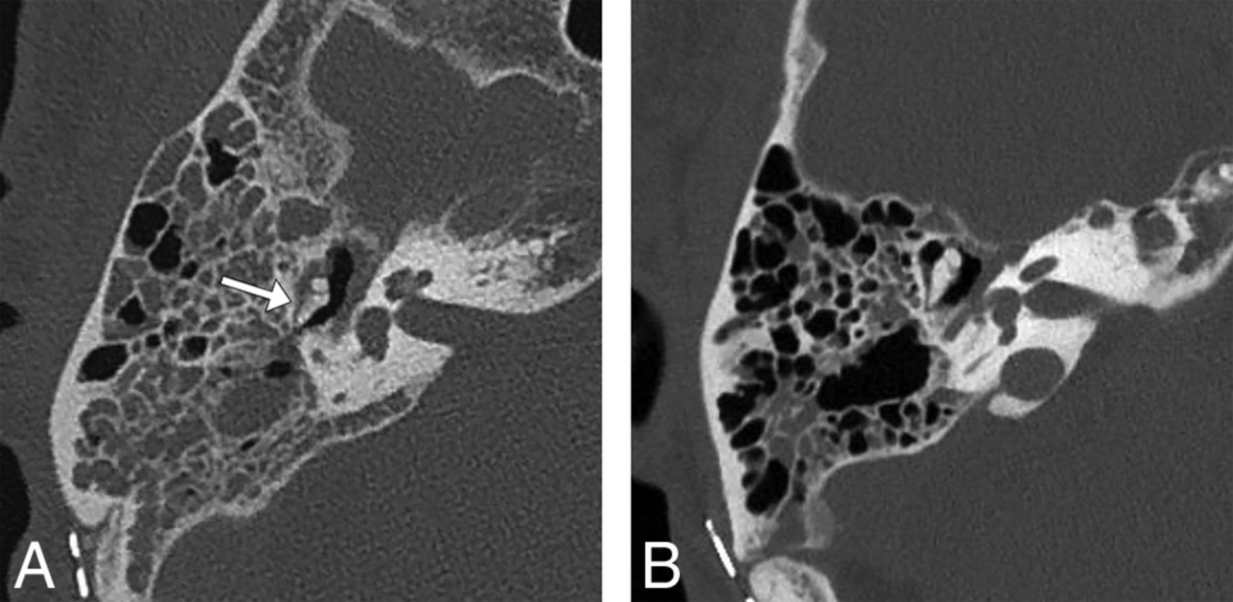
A 64-year-old man status post resection of a right vestibular schwannoma. Right temporal bone noncontrast CT images in bone windows demonstrate a possible perception error when images are reconstructed in random planes. A, Axial image in the acquisition plane obtained before the study intervention with a 29° error angle shows soft tissue in the Prussak space with a hazy appearance of the adjacent incus, suggesting possible erosion of the incus (arrow). B, Axial image in the plane of the lateral semicircular canal as reformatted by a CT technologist 3 months later following the study intervention shows the normal ice cream cone configuration of the malleus and incus with soft tissue in the Prussak space but no evident erosion of the incus, consistent with expected postoperative fluid in the middle ear cavity. The fluid had increased between the 2 examinations (not shown), so the finding is not a result of decreased fluid but a result of volume averaging with the incus body projected in an oblique plane.
This intervention has been favorably viewed by the neuroradiologists in our group, specifically because they anecdotally report now being more able to compare sequential examinations. However, the intervention has resulted in slightly more work for the CT technologists. Some CT technologists have responded favorably, appreciating the opportunity to improve their craft in generating high-value images, while some others have responded unfavorably, finding the process an unwelcome additional task.
Ideally, the reformatted images produced by the automated software system would have produced images in a plane similar to those produced by a technologist, referenced to the lateral semicircular canal. Unfortunately, the automation algorithm available to us was based on a plane referenced to the cochlea, and this plane is, on average, approximately 9° to 10° farther out of plane from the lateral semicircular canal than the planes manually produced in this study. Given that the variance of the manual technologist planes and automated planes was not significantly different, an automated algorithm that references the lateral semicircular canals should be a feasible option in the near future.
The primary limitation of this study is that it was performed at a single institution. However, the intervention was applied across multiple models of CT scanners from 2 different vendors. Additionally, the study was limited by the algorithm of the available automated postprocessing software, which generates imaging planes that reference the cochlea. Ideally, the automated software would have generated images in the plane of the lateral semicircular canal. In that case, a direct comparison of technologist-reformatted and automated image error angles could have been performed with a goal of adopting automated reformats to reduce the need for training of technologists and the time the technologists spend on reformatting images. It is very likely that automated postprocessing software will generate similar or better results than a technologist reformatting the images into the described favored image planes in the near future.
Conclusions
Both technologist and automated reformatting of temporal bone images results in significantly less imaging plane variance compared with images reformatted in the acquisition plane, but manual reformatting remains necessary at our institution, given the preference for standardized planes referencing the lateral semicircular canals. This method of image reformatting is sustainable within our system but will require continued quality assurance due to reasonable expectations of personnel changes across time and to prevent perpetuation of technologists' errors. Further study is suggested to evaluate the effects of standardization of the temporal bone image plane on neuroradiologists' efficiency and perceptual errors. Further work is also suggested to automate image reformatting into planes referencing the lateral semicircular canals.
Footnotes
Disclosures: Jeffrey P. Guenette—UNRELATED: Grants/Grants Pending: American Society of Head and Neck Radiology, Comments: William N. Hanafee 2017 Research Grant.* *Money paid to institution.
REFERENCES
- Received February 5, 2019.
- Accepted after revision May 27, 2019.
- © 2019 by American Journal of Neuroradiology


