
Abstract
BACKGROUND AND PURPOSE: Patients with cerebral aneurysms often undergo MR imaging after microsurgical clipping. Ultra-high-field MR imaging at 7T may provide high diagnostic capability in such clinical situations. However, titanium alloy clips have safety issues such as adverse interactions with static magnetic fields and radiofrequency-induced heating during 7T MR imaging. The purpose of this study was to quantitatively assess temperature increases on various types of titanium alloy aneurysm clips during 7T MR imaging.
MATERIALS AND METHODS: Five types of titanium alloy aneurysm clips were tested, including combinations of short, long, straight, angled, and fenestrated types. Each clip was set in a phantom filled with gelled saline mixed with polyacrylic acid and underwent 7T MR imaging with 3D T1WI with a spoiled gradient recalled acquisition in the steady-state technique. Temperature was chronologically measured at the tips of the clip blade and head, angled part of the clip, and 5 mm from the tip of the clip head using MR imaging–compatible fiber-optic thermometers.
RESULTS: Temperature increases at all locations for right-angled and short straight clips were <1°C. Temperature increases at the angled part for the 45° angled clip and the tip of the clip head for the straight fenestrated clip were >1°C. Temperature increases at all locations for the long straight clip were >2°C.
CONCLUSIONS: Temperature increases on the right-angled and short straight clips remained below the regulatory limit during 7T MR imaging, but temperature increases on the 45° angled, straight fenestrated, and long straight clips exceeded this limit.
ABBREVIATIONS:
- ASTM
- American Society for Testing and Materials
- B1+rms
- root mean square of the MRI effective component of the B1 field
- SAR
- specific absorption rate
- SPGR
- echo-spoiled gradient echo
- TI
- temperature increase
Patients with cerebral aneurysms often undergo MR imaging after microsurgical clipping of the aneurysm. The most common indication for MR imaging after microsurgical clipping is follow-up of the clipped aneurysm and screening for de novo aneurysms.1 MR imaging is also used to assess the presence of cerebral infarction caused by the microsurgical clipping itself or cerebral vasospasm due to SAH.2,3 In addition, MR imaging is used to detect other intracerebral lesions such as brain tumors or cerebrovascular diseases, including cerebral small-vessel disease, which can develop many years after microsurgical clipping.4 MR imaging at 1.5T and 3T has been used as a primary diagnostic tool in such clinical situations. Ultra-high-field MR imaging at 7T is becoming clinically available.5⇓-7 In particular, this imaging technique provides high diagnostic capability and superior evaluation of cerebral microaneurysms,8 the aneurysm dome and neck,9 smaller peripheral blood vessels,10 or perforating arteries.11 These capabilities are equal to angiography via arterial catheterization12 and are superior to lower-field MR imaging.9,10,13
Titanium alloy clips have safety issues such as adverse interactions with static magnetic fields (eg, displacement force and torque) and radiofrequency-induced heating at 7T.14,15 In terms of the former, a short straight clip is reported to be potentially safe when exposed to the 7T MR imaging environment.14 Other investigators have suggested that commercially available aneurysm clips are likely to be safe for patients exposed to an 8T MR imaging system regardless of materials (eg, pure titanium or titanium alloy) and shape.16 For radiofrequency-induced heating, the International Electrotechnical Commission guidelines recommend that the MR imaging equipment should limit the temperature rise in body core temperature and the absolute temperature in local tissues to 0.5°C and 39°C, respectively, for normal operating mode, and to 1°C and 40°C, respectively, for the first level controlled.17 Realistic simulation models have shown that tissue temperature remained below the regulatory limit for short straight clips but exceeded this limit for long straight clips.15,18 However, a variety of aneurysm clips, including short, long, straight, angled, and fenestrated types, are widely used in neurosurgical settings.
The purpose of the present study was to quantitatively assess temperature increases (TIs) on various types of titanium alloy aneurysm clips during 7T MR imaging.
MATERIALS AND METHODS
This study was based on the American Society for Testing and Materials (ASTM) F2182-19e2 “Standard Test Method for Measurement of Radio Frequency Induced Heating On or Near Passive Implants During Magnetic Resonance Imaging.”19
Test Objects
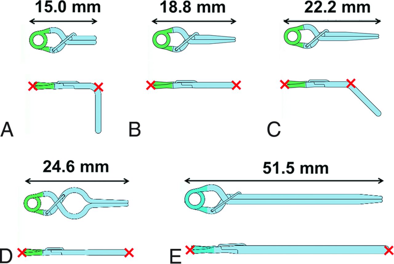
Five types of aneurysm clips were tested, including combinations of short, long, straight, angled, and fenestrated (Fig 1). All clips were made of titanium alloy. Clip length was in the following ascending order: right-angled < short straight < 45°angled < straight fenestrated < long straight.

Schematic drawings of aneurysm clips tested in the present study. Upper row, top view; lower, row, lateral view. Red cross marks denote locations at which the temperature was measured. A, 17–001-22: No. 22, right-angled type. B, 17-001-02: No. 2, short straight type. C, 17-001-49: No. 49, 45°-angled type. D, 17-001-30: No. 30, straight fenestrated type. E, 17-001-92: No. 92, long straight type.
Phantom
This test used a T-shaped plastic head/torso phantom filled with gelled saline (ie, 1.32 g/L of sodium chloride plus 10 g/L of polyacrylic acid in distilled water) (Fig 2A). The weight of the gelled saline in the phantom was 11.1 kg. Two phantoms with the same specifications (including shape and components) were provided. Measured conductivity and relative permittivity in the 2 phantoms were identical (conductivity, 0.517 S/m; relative permittivity, 82.12).

Schematic drawings of an aneurysm clip and fiber-optic thermometer probes in the T-shaped plastic head/torso phantom filled with gelled saline. An aneurysm clip and 4 thermometer probes are set parallel to the static magnetic field (B0) with the implant holder in the phantom so that they are placed 1 cm below the surface of the gelled saline. The closed circle denotes the isocenter of the magnetic field. Cross marks denote locations at which temperature is measured. A, Upper view of the whole phantom. B, Lateral view of the head part of the phantom.
MR Imaging
MR imaging was performed using a 7T MR imaging platform (Discovery MR950; GE Healthcare) with a 2-channel transmit and 32-channel receive head coil (NM008-32-7GE-MR950; Nova Medical). This MR imaging system was used for research only and had received neither approval from the US FDA nor CE certification. ASTM standard protocol F2182-19e2 recommends that a protocol producing relatively high radiofrequency power should be used to achieve the temperature rise to be investigated.19 The echo-spoiled gradient echo (SPGR) technique can change the flip angle, ie, radiofrequency power, and can use a short TR. Thus, SPGR allows easy control of the radiofrequency power. All aneurysm clips were thus scanned using 3D T1WI with an SPGR technique using the following sequence parameters: TE, 0.9 ms; TR, 4.0 ms; FOV, 24.0 cm; section thickness, 2.0 mm; matrix, 64 × 64; number of excitations, 50; number of slices, 102; and scan time, 20 minutes.
The ASTM standard protocol F2182-19e2 recommends performing MR imaging using the maximum value of sequence parameters related to heating such as flip angle, estimated specific absorption rate (SAR), and root mean square of the MR imaging effective component of the B1 field (B1+rms).19,20 Transmitter adjustment was performed automatically by the MR imaging system, with head-averaged SAR and B1+rms calculated as 1.6 W/kg and 3.28 μT, respectively, when the flip angle was set at 37°.
Measurement of Temperature
The temperature in the phantom during MR imaging was measured using 4 MR imaging–compatible fiber-optic thermometer probes with temperature resolutions of 0.1°C and accuracies of ±0.2°C (Neoptix Reflex; Neoptix). Two phantoms, tested clips, thermometer probes, forceps, and digital vernier calipers were left inside the MR imaging room for ≥12 hours before each temperature measurement to equalize the intraphantom temperature with the ambient temperature (19°C–20°C). The MR imaging fan was turned off during scanning.
ASTM standard protocol F2182-19e2 recommends that implants be placed at greater heating positions in the phantom.19 In the present study, the location of maximum B1 was assumed to represent the hottest location. In a pilot study, the location of maximum B1 was determined from 3D actual flip angle imaging.21 That pilot study demonstrated that the point 3.25 cm to the left of the isocenter was the location of maximum B1, and each aneurysm clip was thus placed at this point (Fig 2A).
The temperature of each aneurysm clip set in the phantom was measured using thermometer probes in contact with the clip at the following 2 locations: tip of the clip blade and tip of the clip head for the short straight clip, straight fenestrated clip, and long straight clip; and tip of the clip head and angled part of the clip for the right-angled clip and 45°-angled clip (Fig 1). The third and fourth thermometer probes were set 5 mm from the tip of the clip head and 3.25 cm to the right of the isocenter as a reference, respectively (Fig 2). One investigator removed the implant holder from the phantom and set an aneurysm clip and thermometer probes using forceps. Another investigator confirmed the condition of contact with the thermometer probes and clip. The former investigator measured the distance between the third thermometer probe and the tip of the clip head using digital Vernier Calipers (https://www.sigmaaldrich.com), and the latter investigator confirmed this distance. Temperatures at the 3 locations for each clip were measured simultaneously in a single MR image. An aneurysm clip and 3 thermometer probes were set parallel to the static magnetic field with an implant holder made of acrylic resin in the phantom so that they were placed at 1 cm under the surface of the gelled saline (Fig 2B). Immediately after the end of temperature measurement, 2 investigators confirmed the condition of contact with the clip and measured the distance between the third thermometer probe and the tip of the clip head in the same fashion.
Before temperature measurement of each aneurysm clip, the temperature in the other phantom without aneurysm clips was measured as a control on the same day. This control temperature measurement was performed in the same fashion except for the absence of the clip. Temperature measurements including a combination of absence and presence of an aneurysm clip were performed twice for each clip, and the interval between these 2 conditions for temperature measurement was 2 days. Temperature measurement was performed for only 1 aneurysm clip per day. Each temperature was measured every 2 seconds from 15 minutes before the start of MR imaging to 15 minutes after the end of MR imaging. The SAR averaged for each 6 minutes during MR imaging was also obtained using the scanner console.
Analysis of Temperature
First, for the control temperature without an aneurysm clip, the temperature difference for 5 minutes before the start of MR imaging was averaged as the baseline, and this baseline temperature was subtracted from the temperature at each time point during and after MR imaging. The value at each time point was thus defined as a temperature increase (TI [degree Celsius]), and the maximum TI was determined for each location.
Next, the control temperature without an aneurysm clip was subtracted from the temperature of the aneurysm clip at each time point. The maximum TI for the location of each aneurysm clip was also determined in the same fashion. When the maximum TI was >1°C, sequence parameters related to heating such as flip angle, estimated SAR, and B1+rms were determined to decrease the maximum TI to ≤1°C.
RESULTS
The temperature was successfully measured at all time points. The actual averaged SAR measured for each 6 minutes during MR imaging on the scanner console was 3.0 W/kg.22 This value was higher than head estimated SAR (1.6 W/kg) calculated before measuring the temperature of aneurysm clips but was close to the 3.2 W/kg proposed by the International Electrotechnical Commission as the upper limit.17
The mean (SD) times required to set an aneurysm clip and thermometer probes in the implant holder (the time when the implant holder was outside the phantom) were 5.2 (SD, 0.2 ) minutes and 5.1 (SD, 0.3) minutes for the first and second measurements, respectively. Two investigators confirmed that the condition of contact with the thermometer probes and target clip and the distance between the third thermometer probe and the tip of the clip head remained unchanged from before to after the temperature measurement for all measurements with aneurysm clips.
The maximum TIs in controls measured twice at each location without aneurysm clips are shown in Table 1. Differences in the maximum TI between these 2 measurements (second measurement – first measurement) ranged from −0.5°C to +0.4°C. The maximum TIs at all locations ranged from 1.7°C to 3.3°C (mean, 2.7 [SD, 0.4]°C). The maximum TIs at the reference point were lower than those at other locations except at 5 mm from the tip of the clip head for the long straight clip.
Maximum increase in control temperature measured twice at each location without aneurysm clips
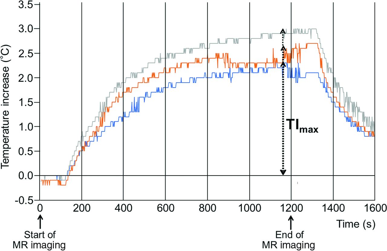
For all 5 types of aneurysm clips, the TI began to increase with the greatest slope 100–400 seconds after the start of scanning, kept increasing during scanning, and peaked between 660 and 1200 seconds after the start of scanning (Fig 3; Online Supplemental Data). The temperature then plateaued for 60 or 120 seconds after the end of MR imaging and subsequently decreased.

Chronological changes in the TI at 3 locations for the long straight clip. TI (degrees Celsius) indicates the difference between temperatures before MR imaging and during or after MR scanning (latter-former). Blue, orange, and gray lines denote the TI at tip of the clip head, tip of the clip blade, and 5 mm from the tip of the clip blade, respectively. TImax indicates maximum TI at each location.
The maximum TIs measured twice at each location are shown in Table 2. Differences in the maximum TI between these 2 measurements (second measurement – first measurement) ranged from −0.2°C to +0.2°C, with the exception of 2 locations for the long straight clip where the absolute value of the difference was ≥0.3°C. The maximum TIs at all locations for the right-angled and short straight clips were <1°C. The maximum TIs at the angled part of the 45°-angled clip and the tip of the clip head for the straight fenestrated clip were >1°C. The maximum TIs at all locations for the long straight clip were >2°C. The maximum TIs at 5 mm from the tip of the head for the long straight clip were >3°C.
Maximum increase in temperature measured twice at each location for each aneurysm clip
For the 45°-angled, straight fenestrated, and long straight clips with a maximum TI of >1°C, sequence parameters related to heating such as flip angle, the estimated SAR, and B1+rms were determined to decrease the TI to <1°C. Such values were calculated as <26°, <0.8 W/kg, and <2.3 μT, respectively, for the 45°-angled and straight fenestrated clips and <14°, <0.2 W/kg, and <1.24 μT, respectively, for the long straight clip.
DISCUSSION
The present study demonstrated that the TI on the right-angled and short straight clips remained below the regulatory limit during 7T MR imaging, but the TI on the 45°-angled, straight fenestrated, and long straight clips exceeded this limit.
For all aneurysm clips, the temperature kept increasing and subsequently plateaued while MR imaging was still underway. The temperature surrounding an aneurysm clip is increased by the radiofrequency during MR imaging but is decreased by the conduction of heat to the gelled saline in the phantom. Combinations of these former and latter effects might have resulted in the present chronological changes in the TI. MR images with the higher energy of radiofrequency than the SPGR used in the present study (eg, fast spin-echo) may induce higher temperatures.
The ASTM F2182-19e2 suggested that marked heating during MR imaging may occur at sharp edges, points, ends of devices, corners, and near the ends of implants.19 In vitro and in silico assessment of radiofrequency-induced heating around the aneurysm clips demonstrated the highest temperatures at both ends of the short straight clip or near the ends of implants.15 The temperature of each aneurysm clip was thus measured at the tip of the clip blade, tip of the clip head, angled part of the clip, and at 5 mm from the tip of the clip head. The TI was <1°C at all locations for the right-angled and short straight clips, >1°C at 1 location for the 45°-angled and straight fenestrated clips, and >1°C at all locations for the long straight clip. These results for the short and long straight clips were comparable with those obtained from in vitro and in silico assessments of radiofrequency-induced heating around aneurysm clips.15,18 The latter assessment also showed that the temperature rose with increasing length of the clip until the length approached 50 mm and the worst-case length was 50 mm.18 When implant length approximates half of a wavelength of radiofrequency on MR imaging, antenna resonance effects may result in substantial increases in temperature.19,23 Half of the wavelength of radiofrequency is 55 mm at 7T24,25 and better approximates the length of the long straight clip (51.5 mm) than other types of clip, a finding that may explain our results.
The present study also showed that for the 45°-angled, straight fenestrated, and long straight clips with a TI of >1°C, when sequence parameters related to heating such as flip angle, estimated SAR, and B1+rms were reduced, the TI decreased below 1°C. However, flip angle reduction involves a reduction in signal intensity,26 and a reduction in the estimated SAR or B1+rms results in a reduced number of slices, prolonging the acquisition time.20 These limitations may preclude clinical use of 7T MR imaging for patients with aneurysmal clips.
The present study has serious limitations. First, the MR imaging system used in the present study was only for research purposes and had not obtained approval from the US FDA and did not have CE certification. However, because the magnitude of the B1+ field was measured during the prescan immediately before each test, the relationship between B1+rms and the degree of temperature rise was considered accurate.27 Second, the thermometer probe placement on the aneurysm clip might have differed subtly between the first and second measurements, even though 2 investigators confirmed the condition of contact with thermometer probes and clips and the distances between the relevant parts before and after temperature measurement for all measurements. Differences in the maximum TI between these 2 measurements ranged from −0.2°C to +0.2°C, with the exception of 2 locations for the long straight clip where the maximum TIs were >2°C.
The accuracies of the thermometer probes used in the present study were ±0.2°C. Differences in positioning of the thermometer probe may have been minimal for the 4 types of aneurysm clips but may have considerably affected temperature measurement for the long straight clip. Third, aneurysm clips parallel to the static magnetic field might not always represent the worst-case orientation for temperature elevation. The electric field distribution and associated currents can differ substantially. Electric field polarization was not measured in the present study. Furthermore, the actual electric field distribution for the human head at 7T is difficult to predict.28 This issue is because radiofrequency wavelengths at 7T are shorter and tissue compartments within the human head are widely heterogeneous, so current distributions in radiofrequency field distributions result in complicated heating patterns.28 In addition, the location of maximum B1 determined from 3D actual flip angle imaging in the present study might not always have been the hottest location.15 Fourth, natural convection in wet tissue and conduction in blood vessels may buffer the TI when these conditions are present at or near the implant location.19 Thus, the TI measured in a phantom is likely to overestimate the actual TI seen in an implant in situ.19 In the brain, CBF and CSF flow may reduce temperature rises compared with phantom measurements. Further studies regarding temperature measurements in animal brains during MR imaging at ≥7T would be of benefit.
CONCLUSIONS
The present study demonstrated that the TIs for right-angled and short straight clips remained below the regulatory limit during 7T MR imaging, but the TIs for the 45°-angled, straight fenestrated, and long straight clips exceeded this limit.
Footnotes
Disclosures: Shouta Tsutsui—UNRELATED: Employment: Iwate Medical University. Makoto Sasaki—UNRELATED: Grants/Grants Pending: Hitachi, GE Healthcare, Idorsia Pharmaceuticals, Actelion*; Payment for Lectures Including Service on Speakers Bureaus: Hitachi, GE Healthcare, Idorsia Pharmaceuticals, Actelion, Ezai, Mesi-physics, Mitsubishi Tanabe, Bayer, Astellas Pharma, Ono Pharmaceutical Co; Royalties: Micron Technology.* *Money paid to the institution.
References
- Received April 1, 2021.
- Accepted after revision May 6, 2022.
- © 2022 by American Journal of Neuroradiology


Jump to section
Related Articles
Cited By...
- No citing articles found.