
Abstract
SUMMARY: The basic principles of scintigraphy are reviewed and extended to 3D imaging. Single-photon emission computed tomography (SPECT) is a sensitive and specific 3D technique to monitor in vivo functional processes in both clinical and preclinical studies. SPECT/CT systems are becoming increasingly common and can provide accurately registered anatomic information as well. In general, SPECT is affected by low photon-collection efficiency, but in brain imaging, not all of the large FOV of clinical gamma cameras is needed: The use of fan- and cone-beam collimation trades off the unused FOV for increased sensitivity and resolution. The design of dedicated cameras aims at increased angular coverage and resolution by minimizing the distance from the patient. The corrections needed for quantitative imaging are challenging but can take advantage of the relative spatial uniformity of attenuation and scatter. Preclinical systems can provide submillimeter resolution in small animal brain imaging with workable sensitivity.
Brain single-photon emission computed tomography (SPECT [also abbreviated as SPET]) is a noninvasive technique, which provides 3D functional information with high sensitivity and specificity. As with all nuclear medicine imaging procedures, it is based on the injection of tracer amounts (nano- to picomoles, ie, much lower than the milli- to micromolar levels that elicit a pharmacologic response) of a molecule labeled with a radioactive isotope. Radioactive decay results in the emission of photons; those that exit the body of the patient unscattered carry information on the location of the decay and, thus, the biodistribution of the radiotracer. Photons are detected with a position-sensitive detector that can provide the incoming location of the photon and its energy to a good approximation, but not the path along which the photon travels, which is necessary to generate projections of the emitting body. Inserting a collimator between the patient and the detector shapes the stream of emitted photons into a beam such that each location on the detector is associated to a line in space along which the decay occurred (often called the line of response [LOR]). The collimator lets pass only photons that approach the detector with certain angles; other photons are (or ideally should be) discarded. Thus, an image is formed at the expense of the rejection of most of the photons emitted. Indeed the sensitivity limitation imposed by the collimator is the single most important factor limiting the performance of SPECT (as usual in the physics literature, from here on the term “sensitivity” is used to mean the fraction of emitted photons that contribute to the image).
A scintigraphy, sometimes called a “planar” study, is obtained when a single view of the patient is acquired. Planar studies are still part of clinical routine: An important example in neurology is brain death scintigraphy.1 Planar studies, however, squeeze 3D information in a 2D projection, so that the contrast between lesion and background is significantly reduced. The projection may also be affected by depth-dependent distortions if a nonparallel geometry is used, as in a pinhole collimator (eg, to improve resolution, sensitivity, or both).
To overcome these limitations, very similar to CT, SPECT uses computer algorithms to combine views from different angles to produce fully 3D images. SPECT has been pursued since the early 60s,2 and brain scanning was one of its first applications3,4; during its infancy, SPECT was the only noninvasive test capable of imaging pathology inside the brain. With time, both whole-body and single-organ systems have been developed, with the heart and the brain receiving the most attention. State-of-the-art systems currently deployed are based on multiple-detector gamma cameras, each with an FOV large enough to scan the width of the body in a single sweep, mounted on a rotating gantry.
Numerous SPECT books5–8 as well as general9–11 and topical12–18 SPECT reviews have been published. Procedure guidelines are also available for the most common studies.1,19 In this article, basic principles are reviewed, with the goal of preparing a discussion of the trade-offs involved in the context of brain SPECT instrumentation design. Special topics include image reconstruction and correction, multiple-isotope studies, and small animal imaging systems.
Isotopes and Radiopharmaceuticals
SPECT isotopes are chosen on the basis of their chemical, biologic, and nuclear properties. Concerning the latter, desirable characteristics include the following: a half-life long enough to allow tracer preparation, injection, and uptake and image acquisition (and possibly imaging at a later time point), but short enough not to deliver an unnecessary dose to the patient (if the biologic half-life of the molecule is not sufficiently short); an energy of the gamma emission sufficiently high to escape from the patient, but sufficiently low to facilitate collimation and detection; and a favorable dosimetry to limit patient exposure.
Many tracers and isotopes have been used in brain SPECT, but only a minority are commonly used. Xenon-133 (133Xe), a diffusible gas, has been used for regional cerebral blood flow (rCBF) imaging as well as Iodine-123 isopropyliodoamphetamine (123I-IMP); these tracers were more recently replaced by the technetium-Tc99m-labeled hexamethylpropyleneamine oxime (Tc99m-HMPAO) and Tc99m-ethyl cysteinate dimer (ECD), because of their uptake, retention, and physical and production characteristics.13 A representative clinical study is shown in Fig. 1. Indium-111 (In 111)- and Tc99m-diethylenetriaminepentaacetic acid, as well as Tc99m-pertechnetate, are used to image CSF. Examples of other tracers are given in the Table and include tracers to measure blood-brain-barrier permeability, image benzodiazepine-receptor binding, serotonin transporters, dopamine receptors and transporters, nicotinic receptors, and β-amyloid plaque and for musculoskeletal and oncologic applications. The reader interested in a thorough discussion is referred to Kung et al.34

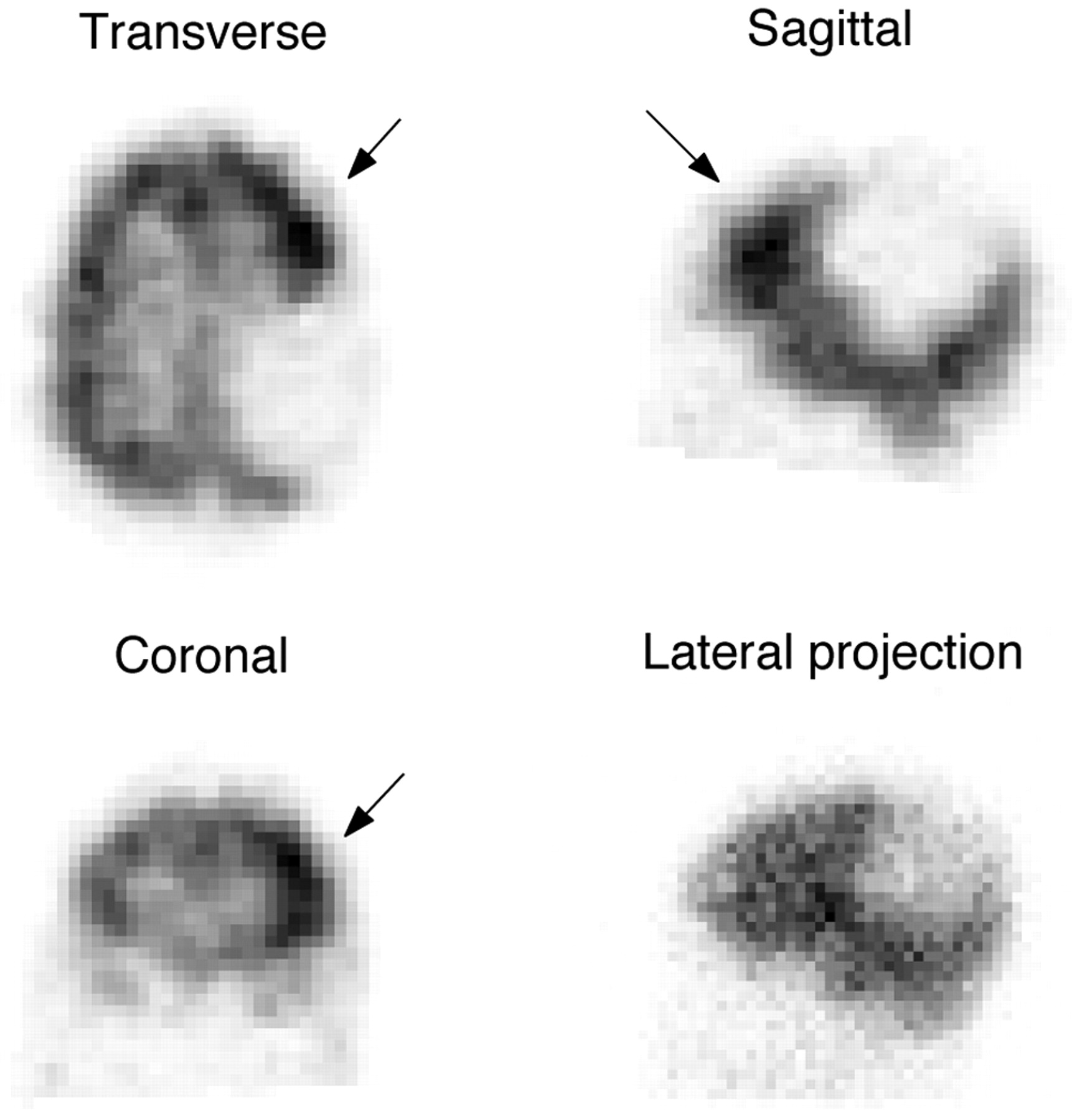
Cerebral perfusion in a 13-year-old boy with a history of seizures. Ictal study following injection of 1.258 GBq (34 mCi) Tc99m-ECD. The image shows a focus of increased uptake in the left frontal lobe (arrows) suggestive of a seizure focus. The photopenic area in the left posterior parietal lobe corresponds to a large cyst previously identified on MR imaging. The increased uptake focus is hardly recognizable in the projection data (bottom right).
Sample brain SPECT compounds and applications
131I is commonly used in targeted radiation therapy applications for its β− emissions, which induce relatively localized damage because of their short range. From an imaging point of view, its γ emission (at 364 keV and as high as 723 keV) is less favorable than the less penetrating Tc99m (140 keV) and 123I (159 keV) photons, but it is still being routinely imaged to verify delivery of the therapeutic dose because it has been historically among the first available and because it still presents cost advantages over the cyclotron-produced 123I.
Comparison to Positron-Emission Tomography
Unlike in SPECT, in positron-emission tomography (PET), radioactive decay results in the simultaneous emission of 2 back-to-back photons. PET determines LORs by coincident detection of these 2 photons and does not need a collimator, thus making much more efficient use of the emitted photons. As a result, PET typically provides much higher sensitivity than SPECT; other advantages include better resolution (with the exception of small animal imaging, especially as used in preclinical neuroscience) and a better potential for quantitative imaging. Some PET isotopes occur among smaller more biologically significant atomic species, such as carbon, oxygen, and nitrogen. However, their short half-life couples their availability to that of a cyclotron or a generator. Even if their inventory is increasing, currently only a minority of tracers are commercially available, starting from fluorine-18 (18F)-based compounds (most notably [18F] fluorodeoxyglucose [18F-FDG]). In some cases, SPECT and PET tracers are equivalent or in direct competition, but in many others, they serve complementary purposes. Despite its shortcomings, today SPECT remains the most common nuclear medicine technique because of its greater availability and reduced cost.
Collimators
Just like the lenses available for reflex cameras, the design of SPECT collimators can be very diverse and should be matched to the imaging problem at hand.
Parallel-Hole Collimators
An excellent analogy for the most common type of collimator, the parallel-hole collimator, is a honeycomb. In fact, collimators are formed by many parallel channels (the cells of the honeycomb), each relatively long and narrow, arranged in a tight and regular lattice. The channels are long and narrow (eg, 25 × 1.5 mm) to restrict the view of the object being imaged as seen from each element of the detector: Ideally, the detector should see through each channel only the activity present along a single straight line passing through the object (ie, a single LOR) (Fig 2). This is equivalent to saying that activity in each part of the object will be imaged only at 1 location on the detector, determined by how the collimator forms the projection of the object. The basic piece of information acquired in scintigraphy (and, thus, in SPECT) is the total activity present along the LOR. This is very similar to CT, in which the basic piece of information acquired is the total x-ray attenuation along the LOR defined by a detector element and the focal spot of the x-ray tube.

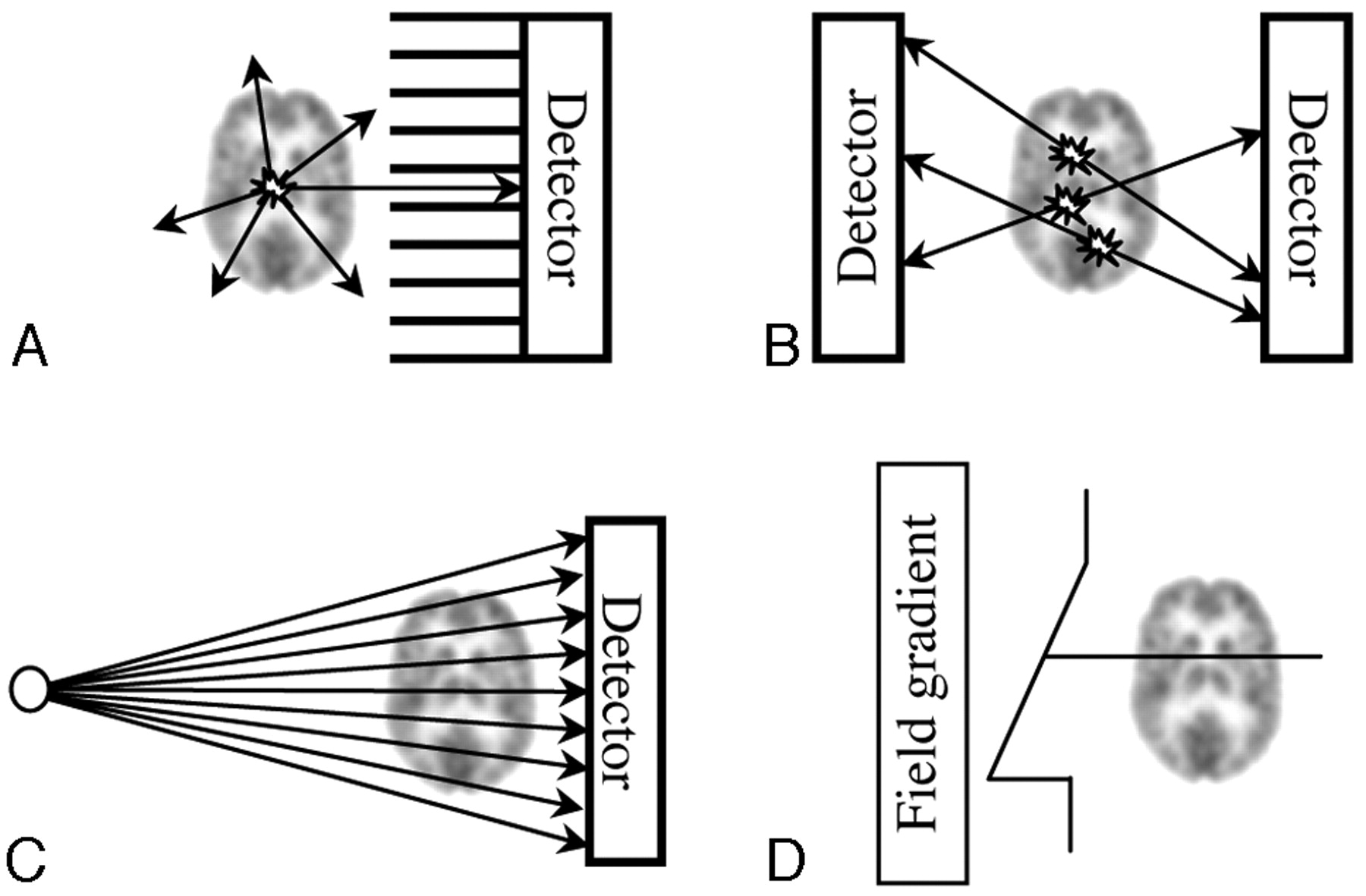
Pictorial view of photon emission and determination of LOR (drawings are not to scale). A, Parallel-hole collimator SPECT. At each point, photons are emitted isotropically. Only those emitted along lines parallel to the channels of the collimator reach the detector. Thus, the direction of the channels of the collimator identifies the LOR. B, In PET, LORs are identified by connecting the location of 2 photons arriving in temporal coincidence at opposing detectors. C, In CT, LORs are determined by the location of detection and the known location of the x-ray beam spot. D, In MR imaging, all spins subject to the same magnetic field have the same precession frequency: Their signal intensity is summed along the lines seeing the same field, just as photons originating along the same line in A, B, or C contribute to the same LOR. Just as in other 3D radiologic techniques, the LOR, or the total signal intensity coming from a line traversing the patient, is the basic piece of information acquired in SPECT from which 3D reconstruction starts.
In practice, of course, the channels of the collimator have a finite width and length, so that photons from lines nearly parallel to each channel are also accepted (Fig 3). This has 2 effects. First, because wider and shorter channels allow more photons to pass, sensitivity increases; this increase improves the counting statistics and, thus, lowers image noise. Second, wider and shorter channels have a wider acceptance angle, which means that they define the LORs more loosely, hurting spatial definition (ie, leading to worse resolution). This trade-off results in a first design choice: high-resolution versus high-sensitivity. A common choice is also a compromise (ie, an all- [or general-] purpose collimator). All of these 3 types of collimators are commercially available, as well as other choices such as ultra-high resolution.

Pictorial view of collimation (drawings are not to scale). A, Parallel-hole collimator. The object is projected onto the detector without magnification. The projection does not use the whole detector. Ideally, photons reach the detector only traveling along lines (LORs, dashed lines) parallel to the collimator channels. B, The finite width of the collimator channels allows lines nearly parallel to the collimator also to reach the detector. C, Longer channels restrict the acceptance angle and resolution improves (see how a more restricted region of space than that in B is seen from each channel). Resolution worsens with distance. D, A fan-beam collimator magnifies the object, projecting it on the whole detector. LORs converge to the focal line (a point in the transverse section shown).
The choice of the right collimator is not obvious. In some cases, it may be dictated by the type of study: If resolution is not important, obviously high sensitivity should be preferred to minimize dose to the patient. In general, however, high resolution improves both spatial detail and contrast, both of which are important, especially when both the presence and the location of a lesion are in question. Indeed, a number of studies suggest that it is usually better to acquire relatively fewer photons at high resolution (ie, with rich positional information) and then trade resolution for decreased noise by smoothing in image processing.12 Use of the highest resolution parallel-hole collimator available has been recommended for perfusion SPECT.19
These considerations apply to all collimators based on channels. The cross-section of the channels may be hexagonal, as in the honeycomb, but it may also be square, circular, or triangular. Further, channels can be arranged in square or hexagonal lattices. These choices impact the fabricability of the collimator more than its response.35,36
Converging Collimators
A more defining characteristic of the collimators is the magnification provided. When all the channels are parallel, the object is projected along parallel lines onto the detector. The projection of the object, thus, has the same size as the object. This is no longer true if the holes converge on a line (fan-beam collimator37–39), a point (cone-beam collimator40–43), or 2 orthogonal lines (astigmatic collimator44,45), often called the “focal line” or “lines” and “focal point” of the collimator. The distance of the focal locus from the collimator is the focal length of the collimator. Magnification depends on the distance of the object from the collimator and is maximal at the focal locus. Both fan- and cone-beam collimators magnify under normal conditions. In a fan-beam collimator, magnification is present only along 1 of the 2 dimensions of the collimator, typically the transverse direction; a cone-beam collimator magnifies along the axial direction as well.
The benefits of magnification are twofold. First, the object is magnified onto the detector, and it is this enlarged projection that is blurred by the nonidealities of the detector (ie, the intrinsic response of the imager). Because the intrinsic response does not depend on the collimator, it always has the same size, and its dimension relative to the object is smaller when it blurs a magnified object. For this reason, in a magnifying geometry, resolution improves.
The second benefit is increased sensitivity. As a point source moves away from a parallel-hole collimator, each channel in the collimator collects fewer photons because of the increasing distance; however, more channels are illuminated. An exact calculation shows that the 2 effects balance each other exactly. Indeed, the sensitivity of a parallel-hole collimator does not change with distance. In a converging geometry, channels are tilted toward the point source. For this reason, as a point source moves away from the detector, the number of illuminated holes increases more than in the parallel-hole case and total sensitivity increases until it reaches a maximum at the focal locus. The increase is more dramatic in the case of a cone beam. Sensitivity and resolution improvements have been shown to translate to increased detectability.46
The price to pay, however, is also twofold. First, in a cone-beam geometry, it is possible that data insufficient (in technical language, incomplete) for 3D reconstruction are acquired. Approaches to this problem are discussed below. Second, the FOV is reduced because it is inversely proportional to magnification: Ideally, at the focal point or line, it is reduced to the focal locus itself. However, state-of-the-art clinical gamma cameras are designed for general applications, one being whole-body scanning. For this reason, at a typical ∼30 × 50 cm, the FOV available is larger than that needed in single-organ imaging. The reason that converging collimators are particularly interesting in brain (or any single-organ) imaging is because they provide the means to implement a trade-off between an unnecessary FOV on one side and sensitivity, resolution, or a blend of both on the other. The use of fan-beam collimators, when available, is recommended in brain SPECT.1,19
Pinhole Collimators
Pinhole collimators have historically been one of the first designs; they are enjoying a lively renaissance because of the recent popularity of small animal imaging. Pinholes share with cone-beam collimators the geometry of the beam. An important difference is that sensitivity is maximal (and the FOV is minimal) next to the collimator, where resolution is best, not at a point removed from it, where resolution is not as good. These properties have made pinholes very successful in small animal imaging47,48 because a limited FOV is sufficient, but they have restricted their use in human studies. An important exception is imaging of therapeutic doses of 131I,49 for which pinholes are particularly interesting because they can be made of special materials and their geometry is more resistant to penetration than collimators based on septa.50,51
Collimator Resolution
As discussed previously, collimator resolution depends on the aspect ratio of the channels, long and narrow channels providing better resolution but worse sensitivity. A characteristic common to all collimators is that resolution worsens with distance from the collimator. In fact, as distance increases, each channel can accept photons from an increasingly wider region of space. To maximize resolution, collimators of any kind must be kept as close as possible to the patient.
In brain imaging, this means that the collimator must clear the bed and the shoulders of the patient. This observation has motivated several proposed solutions (Fig 4): from modifications of the design of clinical cameras52 to the design of special cameras, often in the shape of a helmet53–58; the use of a parallel-hole collimator with slanted channels59,60 (the slant allows the camera to be tilted over the top of the head of the patient, thus avoiding the shoulders); shifting caudally the focal locus of converging collimators42,43; and using half-cone-beam collimators.42 Designs with multiple cameras and parallel-hole collimation (Fig 5) have been compared.61

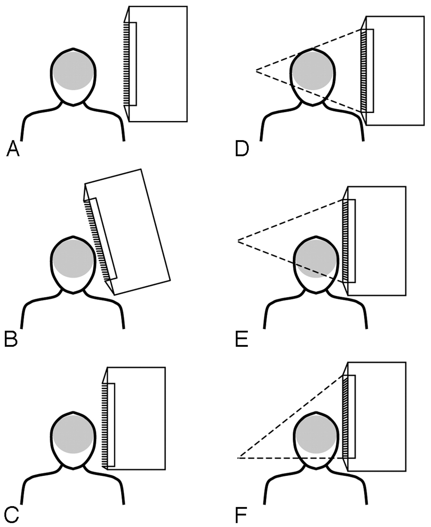
Pictorial representation of the problem of clearing the shoulders of the patient and proposed solutions. A, Due to side shielding and dead area at the borders of the FOV of the detector, collimators do not reach the side of the detector and prevent positioning the camera head next to the patient's head. B, If a parallel-hole with slant holes is used, the camera can be tilted inwards to allow clearance. C, The camera head can be redesigned to minimize side dead space. D and E, The same problem is present for cone-beam collimation, even with minimal side shielding. A possible solution is to tilt the collimator as in B. F, An alternative is to shift caudally the focal point of the collimator. The case in which the shift equals half the size of the collimator, resulting in a half-cone-beam collimator, is shown.

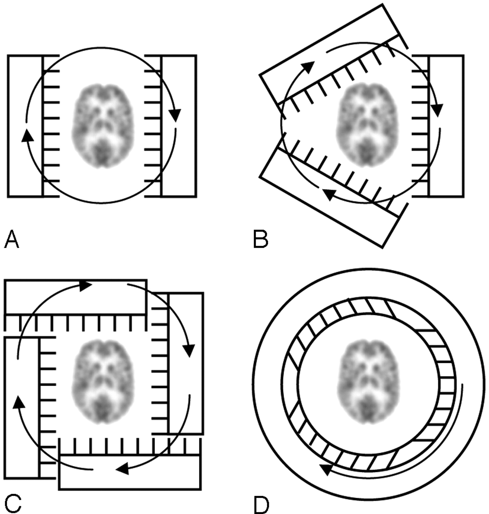
Brain SPECT designs. A, With a dual-head system, the acquisition time can be half that for a single-head camera. B, With a 3-head system, the acquisition time is reduced by a factor of 3. C, Four heads can be offset to allow large-FOV cameras to image close to the head. D, In a ring (helmet) detector, it is possible to rotate only the collimator inside the crystal and shielding.
From a practical point of view, it should also be recalled that because the bed is typically larger than the patient's head, not only does a head holder provide patient comfort and limit patient motion (which can be corrected with more sophisticated methods62) but it can also enable closer positioning because it allows the head of the patient to be placed beyond the end of the bed.
Construction Considerations
Given their function, collimators are made of materials with high stopping power (ie, dense materials with a high atomic number). The most common choices are tungsten, which tends to be expensive and, depending on the application, may be hard to machine or, more commonly, lead. In a common manufacturing technique, lead foils are bent and glued together to form channels; a more expensive alternative is casting, unless mass production is foreseen. In a low-energy collimator (Tc99m, 123I), the septa are only a few tenths of a millimeter thick: Lead septa are very easily bent. If this happens, 1 or more channels can be partially obstructed; this obstruction is readily seen on quality-control images. SPECT collimators are and should be treated as being very fragile which may be demanding because of their substantial weight. The cost of the custom-made collimators encountered in brain applications can be particularly considerable and adds motivation for gentle handling.
Septa must be increasingly thick for medium- (eg, gallium-67 [67Ga]) and high-energy (eg, 131I) isotopes. In these cases, the shadow of the septa becomes obvious in the projections. A possible solution is to rotate the collimator in the plane parallel to the detector during the scan.63
Detectors
The ideal SPECT detector would stop incoming photons with high efficiency and measure their energy and position with accuracy and precision. Gamma cameras are based on coupling a scintillator (a crystal that converts the high-energy photon leaving the patient into many visible light photons) to photomultiplier tubes (PMTs, an electronic component, usually encased in glass, that captures the light generated in the crystal and converts it to an electric current). Sodium iodide doped with thallium (NaI[Tl]) is the scintillator of choice for commercial systems. Bismuth orthogermanate (BGO) is more efficient but offers less spatial and energy resolution and is sometimes also used, whereas lanthanum bromide is a promising new scintillator that is being investigated for its high resolution at a sensitivity comparable to NaI(Tl). All these crystals can be used as a large continuous block (the typical choice of large clinical cameras) or in assemblies of small elements (pixels, usually in smaller preclinical systems). Position-sensitive PMTs, avalanche photodiodes (APDs), charge-coupled devices, or the so-called “silicon PMTs” have been actively investigated but so far have not replaced PMTs in clinical cameras, though preclinical scanners that implement APD readout and pixilated crystal technology are commercially available.
Unlike scintillator technology, solid-state detectors convert photons into a current pulse in a very efficient direct process, which skips the intermediate passage of transformation to visible light. Ultimately, for this reason, solid-state detectors offer the potential for high spatial and energy resolution (which is important in scatter rejection and multiple-isotope studies) and have been the subject of intense research. Results have historically been very encouraging, but eventual application, especially to clinical systems, has been limited by the availability of sufficiently large quantities of material having consistent and stable performance at a reasonable cost. Aside from numerous research systems, preclinical scanners and a dedicated cardiac scanner based on cadmium zinc telluride have recently become commercially available. It is possible that, in the future, solid-state technology will achieve higher penetration of the SPECT market.
A typical state-of-the-art clinical SPECT system comprises 2 or 3 large NaI(Tl) crystals, each with an FOV of approximately 30 × 50 cm (axial × transaxial), 3- to 4-mm intrinsic spatial resolution, and ±14-keV energy resolution for the 140-keV photons of Tc99m (ie, 10% energy resolution). When combined with the resolution of the collimator (the geometric resolution), the intrinsic resolution of the detector gives a total SPECT system resolution of approximately 10 mm and a sensitivity in the order of 1 in 10,000 (10−4). These performance characteristics assume nonoptimized general-purpose collimation and acquisition geometry.
SPECT Acquisition
The collection of SPECT data involves acquiring several views (ie, looking at the object from different angles), typically in 3°–6° steps. Modern SPECT cameras have 2 detectors, all of which have the same function and, indeed, are just replicas of each other. The reason is to increase coverage and so acquire the same data twice as fast. Because the detectors, their shielding, and the associated collimators are very heavy, multiple heads also conveniently counterbalance the system. Three-head systems64 have been introduced by a number of manufacturers, and at least one 4-head system has been developed (Fig 5).65
Theorems are available that detail the necessary and sufficient conditions that the data must satisfy to allow artifact-free reconstruction of the object. These conditions are very simple for collimators in which different axial planes are acquired independently.66 This is the case of the parallel- and fan-beam collimators, in which all LORs belong to some axial plane (ie, a plane normal to the axis of rotation); cone-beam and pinhole collimators provide concrete counterexamples.
In the first case, application of the theorems is rather straightforward and leads to the conclusion that data must be acquired from at least 180°, plus an overscanning equal to the aperture angle of the fan-beam if LORs are not parallel. This condition applies to all planes because all planes present the same geometry. Consequently, only a rotation around the object is needed to acquire complete data along the entire axial FOV of the detector; no movement along the axis of rotation is needed. This fact, along with the previous observation that resolution is always best in the proximity of the collimator, provides the justification for 2 types of orbits often used in SPECT scanning. First, the use of a circular orbit around, say, the torso of the patient unnecessarily limits the distance of approach to the patient's widest dimension for all view angles. Modern scanners can implement body-contour orbits, which in their simplest version are elliptic. The user selects the long (usually from the anteroposterior views in brain scanning, but from the lateral views in whole-body scanning) and the short axis of the ellipse by positioning the camera around the patient; the orbit is memorized and scanning begins. With this orbit, views taken along the short axis are not limited to the resolution of views taken along the long axis. Second, the heads of the camera are typically placed opposite to each other, and a 180° rotation of each detector is executed. With this protocol, data are actually collected from 360°, which at a first sight is redundant because each detector collects separately all the information necessary for reconstruction. However, in practice, opposite views actually provide different information, not only because acquiring from opposite sides of the patient provides better resolution, once on one side and once on the other, but also because scattering and attenuation affect opposing views in different ways.
A different situation is encountered in heart scanning, in which case the detectors are not placed opposite to each other, but at a relative 90°, and then are rotated by 90°. With this protocol, each head acquires 90° worth of data for the total 180° needed (right anterior oblique to left posterior oblique). Other things being equal, scanning time is halved, and resolution is best because data are always acquired next to the organ of interest. This protocol has been recommended by the American Society of Nuclear Cardiology,67 but it has recently been challenged on the basis that artifacts commonly seen in clinical experience and phantom studies may arise from acquiring data with high resolution only on 1 side of the patient, giving rise to an asymmetry that ultimately results in “increased nonhomogeneity and inconsistent defect size quantification.”68,69 In brain scanning, all views are equally important and a 360° collection is in order.
The case in which LORs not lying on an axial plane are acquired is more challenging and involves applying, in a fully 3D geometry (ie, one that cannot be decomposed in replicas of the same transaxial plane), Tuy condition70: In brief, data can provide artifact-free reconstruction at a point if all planes passing through that point intersect the curve described by the focal point during scanning. For example, if a pinhole or a cone beam scans the patient along a classic planar circular orbit, all points in the plane of the orbit can be reconstructed artifact-free; however, points in any other plane cannot be reconstructed because at least the plane passing through the point and parallel to the plane of the orbit does not intersect the orbit of the pinhole, which is the focal point of the beam. Experimentally axial blurring corrupts the image outside the plane of the orbit.71
A possible solution is the use of nonplanar orbits, the most obvious choice being a helical orbit,72 which, in principle, can be conveniently obtained by moving the patient's bed during the scanning and synchronizing its motion with the rotation of the heads. Helical orbits are implemented in commercial preclinical systems and have been proposed for clinical scanning in combination with half-cone-beam collimation.71 Other solutions include offsetting the focal point of the cone beam73 or using 2 circular orbits.72,74 Yet another possibility is to use a cone-beam collimator on 1 of the heads of the camera to achieve high sensitivity and a parallel- or fan-beam collimator on the other to acquire at least 1 complete dataset.75
SPECT/CT
Despite having been the first dual-modality system,76 SPECT/CT has gained popularity only following the success of PET/CT systems.
SPECT/CT offers the nearly simultaneous acquisition of anatomic and functional information, with image registration capabilities better than those possible with data acquisition on separate scanners followed by image reorientation.77,78 Accurate coregistration is particularly valuable in treatment planning. Scanners that mount external sources (eg, gadolinium-153) for the measurement of attenuation along all LORs provide precious additional information for attenuation correction while adding <1% to the patient dose burden79; in this line of development, SPECT/CT is expected to lead to even further advances but at a significant cost in dose unless CT is otherwise indicated. All 3 major manufacturers currently offer SPECT/CT systems. Increased cost and footprint are among the possible disadvantages.
Image Reconstruction
The acquired data can be reconstructed via analytic algorithms, typically filtered back projection (FBP) or, increasingly commonly, by iterative methods. For a general overview of SPECT reconstruction methods, recent reviews are available.80
Analytic Methods
In FBP, projection data are first assigned a proper weight, determined by the filter selected, and then projected along straight lines back into the reconstruction FOV. FBP provides fast reconstruction but does not handle the noisy data of SPECT well, often resulting in streaky images. A detailed and nonmathematic review of FBP for SPECT can be found in Groch and Erwin.10
The simplest filter, called a ramp filter, can reconstruct the image exactly in the absence of noise (and of all nonidealities previously encountered) but amplifies it when noise is present, which is always the case in reality. Different filters have been designed to allow trading off noise reduction for high resolution and to better manage the ringing artifacts due to the abrupt frequency cutoff of the ramp filter. In brain perfusion imaging, the ramp filter remains a good place to start because of the importance of high resolution81; a Butterworth filter can then be used to smooth the image, which has been shown to increase detectability.82
Fan-beam reconstruction can be accomplished by rearranging the LORs as if they had been acquired in a parallel-beam geometry83; several research efforts have refined the quality and expanded the applicability of fan-beam algorithms.84
Cone-beam-algorithm research enjoys considerable synergy with the CT community. The most common algorithm used is based on a circular orbit and, thus, is affected by axial blurring.85 As discussed, necessary and sufficient conditions for artifact-free reconstruction have been given: Exact methods must rely on other orbits. Being unable to visit and cite at least a part of the considerable work done in the area is unfortunate. A recent contribution is Pack et al86; a general framework has been provided in Zhao et al.87 In the specific context of brain studies, the work of Tang et el88 on analytic reconstruction of cone-beam data must be mentioned.
Iterative Methods
Iterative reconstruction has the significant advantage of being able to model, not just manage, noise as well as scatter, attenuation, and other nonidealities, such as collimator penetration and depth-dependent resolution. Unfortunately, this richness and versatility comes at the price of significantly longer reconstruction times, which modern clinical computers are starting to reduce to practical waiting times. Several iterative algorithms have been proposed.89–94
Iterative image reconstruction starts from an initial guess of the distribution of activity over the FOV (usually uniform) and then compares the projections that would have resulted from this distribution with those that were actually obtained. This comparison is used to update the guess, and the process is then repeated until the estimated projections converge to those actually obtained. Convergence is typically slow, and acceleration methods have been developed.92 The choice of the optimal number of iterations is not trivial: Too few will result in incomplete convergence; too many, in noisy images.
In the presence of noise, it will always be impossible to reconstruct exactly the object that generated the data. Maximum likelihood algorithms seek the activity distribution most likely to have generated the experimental realization of the data. Other algorithms impose similar or other conditions; for example, to limit noise amplification with iteration, algorithms that seek smooth solutions to the problem have been introduced.
Quantitative Imaging
The ultimate promise of nuclear imaging techniques is to provide in vivo absolute measurements of physical quantities such as isotope concentration. To achieve this goal, one must account for all the nonidealities mentioned in the previous section, as well as others such as partial volume effects.
A very considerable literature is available on how to perform these corrections, which are increasingly becoming part of image-reconstruction protocols. It is impossible even to summarize these methods in a nonspecialized review. In the following, it is possible to provide reference to only a few sample studies, selected with no other criterion than representativeness of a much larger group. In broad terms, brain SPECT constitutes a simpler case than cardiac SPECT because hypothesizing uniform attenuation throughout the imaging volume does not lead to obvious errors. For example, attenuation correction can be effectively performed starting from the emission image and assuming uniform attenuation9,95,96; however, some studies suggest the necessity of transmission data.97 More sophisticated methods have usually been developed with reference to cardiac imaging98 but, in principle, apply to brain scanning as well. Scatter99 and partial volume100,101 corrections are more problematic. Of course, accurate reconstruction is also strictly related to the routine quality-control procedures, starting from the check of uniformity, linearity, and center of rotation. When fan-beam collimation is used, additional calibration of the focal length and the position of the focal locus should be implemented.102 Interested readers are referred to a recent comprehensive review.103
In general, it has been shown that applying all corrections improves the ability to quantify,104–107 but results can be problematic because artifacts108 or noise109 may be introduced in the correction process.110 The methods that have been developed in the research arena are increasingly finding their way into commercial systems.111
Multiple-Isotope Imaging
If different molecules are labeled with SPECT isotopes having different γ emission, it is possible to follow different metabolic processes simultaneously. For example, Tc99m-HMPAO can be used to monitor perfusion, whereas a 123I-based compound is used to study different phases of dopamine transmission.112 Other combinations of 2113,114 or 3 isotopes have also been used.115
This capability is fairly unique to SPECT. It presents its own challenges and has been one of the motivations to pursue high-energy-resolution detectors, which allow better separation of the signal intensity from the different isotopes.
Small Animal Imaging
In the last decade, interest in imaging small animals has gained significant momentum, especially in relation to the development of new pharmaceuticals. In vivo imaging allows longitudinal studies in which each animal essentially serves as its own control, greatly reducing the large number of animals otherwise needed for statistical significance.
Both animal PET and SPECT systems have now been commercialized. As discussed, SPECT systems are usually based on (multiple-)116,117 pinhole118 geometry, but other designs have also been proposed.119 Some systems are adaptations of clinical cameras, but most are stand-alone systems. Most interesting, in SPECT, resolution is not limited by the size of the crystals making the detector or by the positron range. Resolutions of a few hundred micrometers have been experimentally demonstrated.120 In small animals, corrections for attenuation and scatter are not as important as in human studies, but the reduced scale of the problem emphasizes other factors, such as collimator penetration and the need for accurate calibrations of the system, especially those based on adaptations of clinical cameras.
As in human brain imaging, resolution and sensitivity performance are best when it is possible to focus on a single organ. The technique has been eloquently demonstrated in small animal brain imaging.119
As ever-finer resolutions are pursued, it should be recalled that to every resolution improvement by a factor of 2, a sensitivity increase by a factor of 16 must follow to maintain the same image noise level.121 In the future, the limit on the activity and activity concentration that can be injected without altering the significance of the experiment (currently it is not uncommon to inject in mice total activities not far from those used clinically in humans) will be the factor most likely to limit the performance of preclinical imagers.
Appendix: Collimator Characteristic Equations
Mathematical expressions of the resolution, sensitivity, and FOV of different collimators help visualizing and quantifying design trade-offs. For example, for a fan-beam collimator, system resolution is obtained from the collimator (geometric) and intrinsic (detector) component from  1) where H is the distance from the detector side of the collimator, d is the width of the channels, a is their length, FWHMi is the intrinsic resolution of the detector, and m = (F + a) / (F + a−H) is the magnification, with F the focal length of the collimator. Because resolution is measured as the width of the point spread function, a small value of λs signifies good resolution. Sensitivity is given by
  2) where t is the thickness of the septa and θ is the incidence angle at the detector. Finally, the FOV is
  3) where D is the size of the detector corresponding to the dimension along which the FOV is measured.
From these equations, it is possible to quantify several qualitative observations proposed in the text. For example, a large distance from the collimator H worsens resolution; a low d / a ratio (small long channels) improves resolution at the expense of sensitivity; and a high magnification improves resolution and sensitivity at the same time, but reduces the FOV.
References
- Copyright © American Society of Neuroradiology


